


SECTION 4—FRONT RIGGINGS
Tracer
®
IV 28 Part No. 1110558
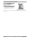
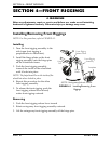
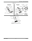
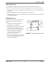
5. Adjustthefootplateassemblyheightbyaligningthedesiredadjustmentholesinthe
upperfrontriggingsupportandlowerfootplateassembly.
6. Fromtheoutsideoftheswingawayfrontrigging,insertthethreadedrivetthrough
boththefrontriggingsupportandthefootplateassembly.
7. Fromtheinsideoftheswingawayfrontrigging,insertthebuttonheadscrewthrough
theappropriateadjustmentholeandthreadintothethreadedrivet.
8. Usingascrewdrivertoholdthethreadedrivetinposition,securelytightenthebutton
headscrew.Torqueto32in‐lbs.
9. Rotatecamlockleverdowntolockedposition.
10. RepeatSTEPS1‐9toadjusttheremainingfootrest.
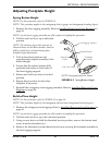
FIGURE 4.3 Bolt-In-Place Height
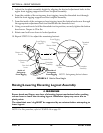
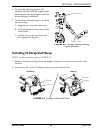
Raising/Lowering Elevating Legrest Assembly
ƽ WARNING
Ensure hands and fingers are clear of elevating legrest mechanism before pushing
release lever to lower the elevating legrest. Otherwise injury may occur due to
pinch points.
The wheelchair user’s leg MUST be supported by an assistant before attempting to
lower legrest.
NOTE:Forthisprocedure,refertoFIGURE 4.4onpage29.
Front Rigging
Support
Button Head
Screw
Threaded Rivet
Footplate
Assembly
NOTE:Swingawayfootrestshown.
Footplate
Assembly
Threaded
Rivet
Front Rigging
Support
Button Head
Screw
Adjustment
Hole
Inside of
Swingaway
Front Rigging
Adjustment
Hole
Cam Lock
Lever
Outside of
Swingaway
Front Rigging