


SECTION 4—FRONT RIGGINGS
Part No. 1110558 27 Tracer
®
IV
Adjusting Footplate Height
Spring Button Height
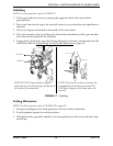
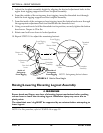
NOTE:Forthisprocedure,refertoFIGURE 4.2.
NOTE:Thisprocedureappliestotheswingawayfrontriggingsandswingawayelevatinglegrest.
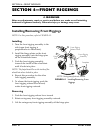
1. Removethefrontriggingassembly.RefertoInstalling/RemovingFrontRiggingson
page 26.
NOTE:Laythefrontriggingassemblyonaflatsurfacetosimplifythisprocedure.
2. Pullthecamlockleveruptounlocked
position.
NOTE:Theelevatinglegresthastwosetsof
releasebuttons,onesetabovetheother.Eachset
willbevisibleoneatatimeallowingfiner
footplateheightadjustment.
3. Pushinthereleasebuttonsand
repositionthefootplateassemblytothe
desiredheight.
4. Ensurethatthereleasebuttonsfully
protrudefromholesonbothsidesof
thefrontriggingsupport.
5. Rotatecamlockleverdowntolocked
position.
6. Repeatthisprocedurefortheother
footplate,ifnecessary.
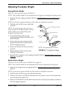
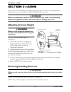
FIGURE 4.2 Spring Button Height
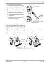
7. Reinstalltheswingawayfrontriggingassembly.RefertoInstalling/RemovingFront
Riggingsonpage 26.
Bolt-In-Place Height
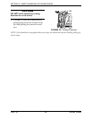
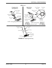
NOTE:Forthisprocedure,refertoFIGURE 4.3onpage28.
NOTE:Thisprocedureappliestotheswingawayfootrestsandswingawayelevatinglegrest.
1. Removetheswingawayfrontrigging.RefertoInstalling/RemovingFrontRiggingson
page 26.
NOTE:Laythefrontriggingassemblyonaflatsurfacetosimplifythisprocedure.
2. Pullthecamlockleveruptotheunlockedposition.
3. Usingascrewdrivertoholdthethreadedrivetinposition,removethebuttonhead
screwfromthethreadedrivet.
4. Removethethreadedrivetandbutton
headscrewsecuringthefootplateassemblyto
thefrontriggingsupport.
Front Rigging Support
Release Button
Footplate
Assembly
Cam Lock Lever
Adjustment
Holes
NOTE:Swingawayfootrestshown.