


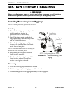

SECTION 4—FRONT RIGGINGS
Tracer
®
IV 30 Part No. 1110558
Replacing Heel Loop
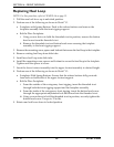
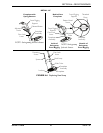
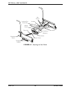
NOTE:Forthisprocedure,refertoFIGURE 4.6onpage31.
1. Pullthecamlockleveruptounlockedposition.
2. PerformoneofthefollowingasshowninDetailʺAʺ.
• FootplateswithSpringButtons:Pushinthereleasebuttonsandremovethe
footplateassemblyfromthefrontriggingsupport.
•Bolt‐In‐PlaceFootplates:
i. Usingascrewdrivertoholdthethreadedrivetinposition,removethebutton
headscrewfromthethreadedrivet.
ii. Removethethreadedrivetandbuttonheadscrewsecuringthefootplate
assemblytothefrontriggingsupport.
3. Removethemountingscrew,space randlocknutthatsecuretheheellooptothe fo otplate.
4. Removeexistingheelloopfromslidetube.
5. Installnewheelloopontoslidetube.
6. Installthemountingscrew,spacerandlocknuttosecuretheheellooptothefootplate.
Tightenuntilthespacerissecure.
7. Insertthelowerfootrestassemblyintotheupperfootrestassemblytodesiredheight.
8. PerformoneofthefollowingasshowninDetailʺAʺ:
• FootplatesWithSpringButtons:Ensurethatthereleasebuttonsfullyprotrude
fromholesonbothsidesoftheupperfootrestsupport.
•Bolt‐In‐PlaceFootplates:
i. Fromtheoutsideoftheswingawayfrontrigging,insertthethreadedrivet
throughboththefrontriggingsupportandthefootplateassembly.
ii. Fromtheinsideoftheswingawayfrontrigging,insertthebuttonheadscrew
throughtheappropriateadjustmentholeandthreadintothethreadedrivet.
iii. Usingascrewdrivertoholdthethreadedrivetinposition,securelytightenthe
buttonheadscrew.Torqueto32in‐lbs.
9. Rotatecamlockleverdownto
lockedposition.