


Tracer® EXI 38 Part No. 1110547
ANTI-TIPPERS/WHEEL LOCKSSECTION 8
ANTI-TIPPERS/WHEEL LOCKS
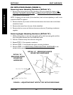
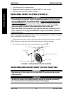
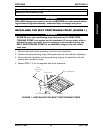
NOTE: Any wheel lock adjustment should embed the wheel lock shoe at least 1/8-inch (3/16-inch
if pneumatic tire) into the tire when engaged.
7. Repeat STEPS 1-6 until the wheel lock shoe embeds the tire 1/8-inch (3/16-inch for
other tires) and HOLDS the wheelchair in place when pushed.
8. If the measurement of 1/8-inch (3/16-inch for other tires) can not be achieved,
remove the bolt and locknut that secure the wheel lock to the wheelchair frame and
mount the wheel lock in the remaining mounting position.
9. Repeat STEPS 1-7
10. If wheel lock is unable to properly
engage the wheel it may be necessary
to install wheel lock shoe extensions.
Refer to
INSTALLING WHEEL LOCK
SHOE EXTENSIONS in this sectoion
of the manual.
11. Repeat STEPS 1-7
12. Repeat STEPS 1-10 for the opposite
wheel lock.
13. Engage both wheel locks and ensusre
the occupied wheelchair is held in
place when pushed.
WARNING
If wheel locks do not hold the occu-
pied wheelchair in place contact a
qualified technician. - other wise
injury or damage may occur.
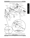
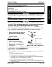
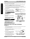
FIGURE 4 - ADJUSTING THE
PATIENT OPERATED WHEEL
LOCKS
DETAIL "A" -
WHEEL LOCK
SHOE
ENGAGEMENT
1/8-inch
(3/16-inch
pneumatic tires)
Tire
Wheel Lock
Shoe
Wheel Lock Handle
Bolt and Locknut
Mounting Positions
Wheel
Lock
Shoe
Rear
Wheel
Wheel
Lock
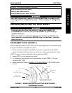
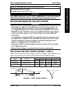
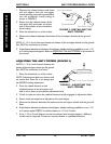
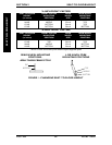
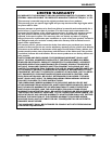
INSTALLING WHEEL LOCK SHOE EXTENSIONS
(FIGURE 5)
1. Loosen the two (2) set screws on the wheel lock shoe extension until the set screws
do not protrude into the slot.
2. Insert the disk wheel lock shoe into the slot in the shoe extension.
NOTE: Ensure the pointed end of the
wheel lock shoe extension is facing toward
the rear wheel.
3. Position the wheel lock shoe exten-
sion so the outside edge is flush with
the end of the wheel lock shoe.
4. Securely tighten the two (2) set screws
to secure the wheel lock shoe exten-
sion to the wheel lock shoes.
Slot
Set
Screws
Pointed End of
Wheel Lock Shoe
Extension
Wheel Lock Shoe Extension
FIGURE 5 - INSTALLING WHEEL
LOCK SHOE EXTENSION