


Tracer® EXI 24 Part No. 1110547
SECTION 3 FRONT RIGGINGS
FRONT RIGGINGS
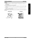
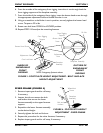
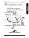
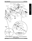
HEEL LOOP REPLACEMENT (FIGURE 6)
1. Pull the cam lock lever UP to UNLOCKED position.
2. Perform one (1) of the following as shown in DETAIL "A" of FIGURE 6:
A. FOOTPLATES WITH SPRING BUTTONS:Push IN the release buttons and
remove the footplate assembly from the front rigging support.
B. BOLT-IN-PLACE FOOTPLATES:
Using a screw driver to hold the riv nut in position, remove the button head
screw from the rive nut.
Remove the riv nut and button head screw securing the footplate assembly to
the front rigging support.
3. Remove the mounting screw, spacer and locknut that secure the heel loop to the
footplate.
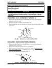
4. Remove EXISTING heel loop from slide tube.
5. Install NEW heel loop onto slide tube.
6. Install the mounting screw, spacer and locknut to secure the heel loop to the
footplate Tighten until the spacer is secure.
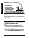
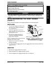
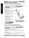
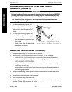
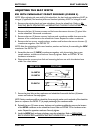
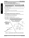
RAISING/LOWERING THE ELEVATING LEGREST
ASSEMBLY (FIGURE 5)
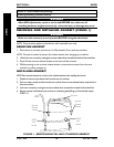
WARNING
Ensure hands and fingers are clear of elevating legrest mechanism BEFORE
pushing release lever to lower the elevating legrest. Otherwise injury may
occur due to pinch points.
The wheelchair users leg MUST be supported by an assistant BEFORE
attempting to lower legrest.
1. To raise the elevating legrest, the
assistant should grab hold of the
support tube and raise elevating leg-
rests until the desired height is ob-
tained.
2. To lower the elevating legrest, per-
form the following:
A. Support user leg with one (1) hand.
B. Push release lever downward with
other hand.
C. Gently, lower user leg down and
rest against the legrest.
FIGURE 5 - ADJUSTING THE
ELEVATING LEGREST ASSEMBLY
Support Tube
Release
Lever