


Part No. 1110547 23 Tracer® EXI
SECTION 3FRONT RIGGINGS
FRONT RIGGINGS
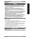
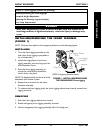
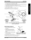
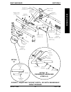
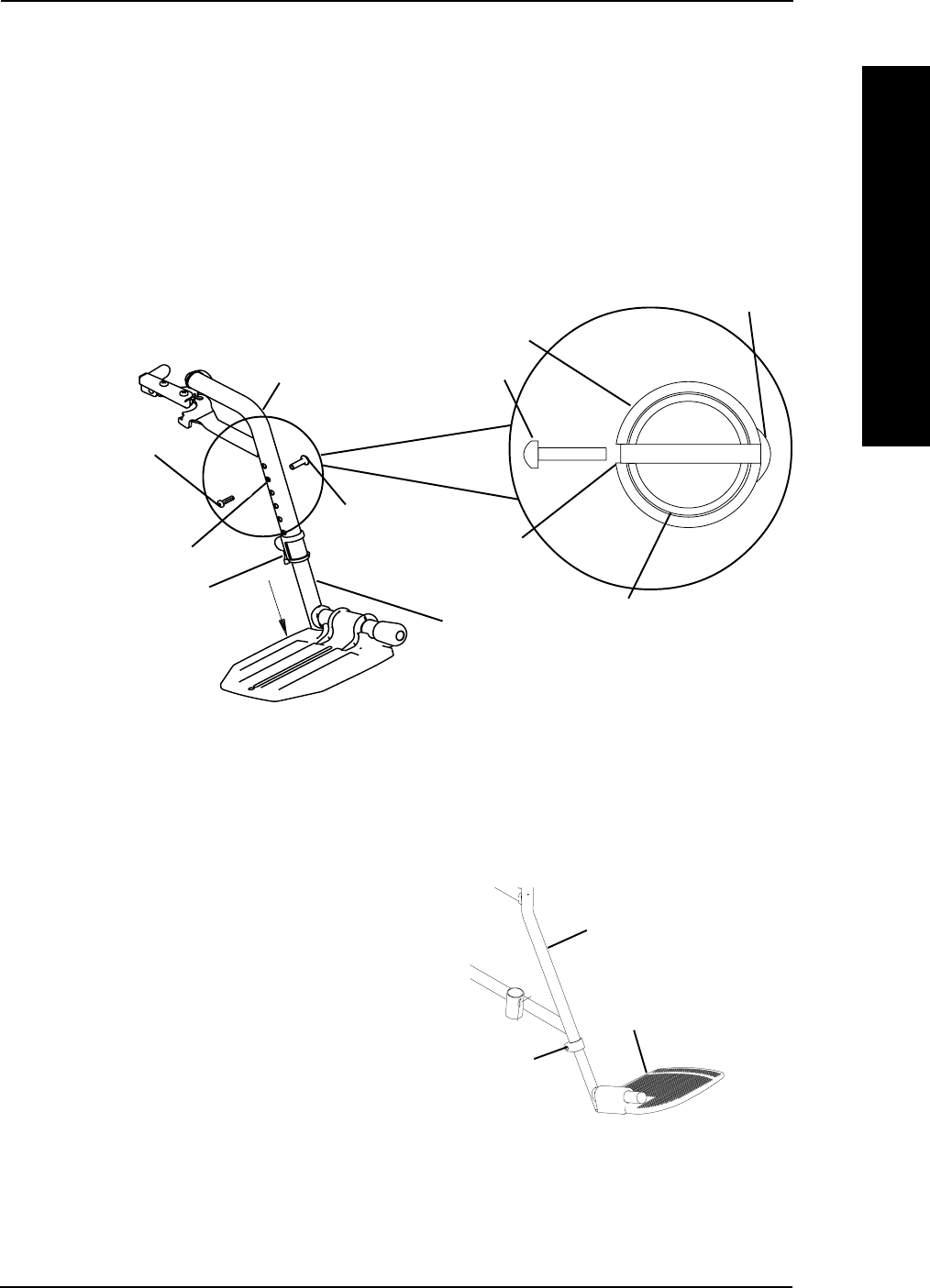
FIGURE 3 - FOOTPLATE HEIGHT ADJUSTMENT - BOLT-IN-PLACE
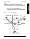
HEIGHT ADJUSTMENT
6. From the outside of the swingaway front rigging, insert the riv nut through both the
front rigging support and the footplate assembly.
7. From the inside of the swingaway front rigging, insert the button head screw through
the appropreate adjustment hole and thread into the riv nut.
8. Using a screwdriver to hold the riv nut in position, securely tighten the button head
screw. Torque to 32 in-lbs.
9. Rotate cam lock lever DOWN to LOCKED position.
10. Repeat STEPS 1-8 to adjust the remaining footrest.
OUTSIDE OF
SWINGAWAY
FRONT
RIGGING
Riv Nut
INSIDE OF
SWINGAWAY
FRONT
RIGGING
Button Head Screw
Footplate
Assembly
Front Rigging
Support
Cam Lock Lever
Adjustment Hole
NOTE: Swingaway footrests shown.
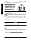
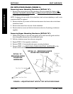
Riv Nut
Button Head
Screw
Footplate Assembly
Front Rigging
Support
Adjustment
Hole
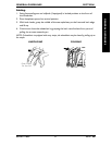
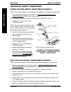
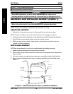
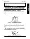
FIXED FRAME (FIGURE 4)
1. Remove impact guards and/or calf strap,
if necessary.
2. Loosen, but do not remove the bolt
and locknut that secure the lower
footrest assembly to the upper footrest
support.
3. Reposition the lower footrest assembly
to the desired height.
4. Securely tighten the bolt and locknut.
5. Repeat this procedure for the other footrest, if necessary.
6. Replace impact guards and/or calf strap, if necessary.
Bolt and
Locknut
Wheelchair
Frame
Footplate
Assembly
FIGURE 4 - FOOTPLATE HEIGHT
ADJUSTMENT - FIXED FRAME