


Part No. 1104849 77 3G Storm Series
®
Wheelchairs
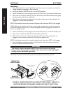
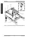
22NF BATTERIES (FIGURE 2)
Removing.
1. Remove the battery boxes. Refer to REMOVING/INSTALLING BATTERY BOXES
in SECTION 9 of this manual.
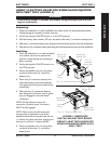
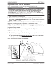
2. Cut the tie wrap that secures the rear portion of the wiring harness and joystick
cable to the rear of the seat frame (DETAIL “A”).
3. Perform one (1) of the following sections:
WHEELCHAIRS WITH MOTOR/GEARBOX ASSEMBLY
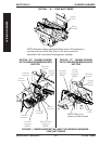
A. Cut TIE-WRAPS A and B that secure the two (2) motor/controller
connections and the controller/wiring harness connection (BLUE connectors)
together (DETAIL “B”).
B. Cut TIE-WRAP C that secures the battery charger cable, motor connector
cable, controller connector cable, and wiring harness cable to the base frame
(DETAIL “B”).
WHEELCHAIRS WITH GEARLESS/BRUSHLESS MOTOR
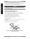
A. Cut TIE-WRAP A that secures the battery charger cable to the base frame
(DETAIL “C”).
NOTE: For STEPS 4-6 refer to Detail “B” or “C”.
4. Disconnect the battery harness/charger cable (BLUE) from the controller connector (BLUE).
5. Remove the two mounting screws that secure the charger cable to the mounting bracket.
6. Remove the wiring harness.
Installing.
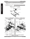
1. Secure the charger cable to the mounting bracket with the two (2) mounting
screws. Securely tighten (DETAIL “B” or “C”).
2. Connect the battery harness/charger cable (BLUE) to the controller connector
(BLUE) (DETAIL “B” or “C”).
3. Perform one (1) of the following sections:
WHEELCHAIRS WITH MOTOR/GEARBOX ASSEMBLY
A. Group the two (2) motor/controller connections together along with the
controller/wiring harness connection (BLUE) and secure with TIE-WRAPS A
and B (DETAIL “B”).
B. Secure the Wiring Harness Cable, Battery Charger Cable, Controller Connector
Cable, and Motor Connector Cable to the suspension arm with TIE-WRAP C
(DETAIL “B”).
WHEELCHAIRS WITH GEARLESS/BRUSHLESS MOTOR OPTION:
A. Secures the battery charger cable to the base frame with TIE-WRAP A
(DETAIL “C”).
4. Tie-wrap NEW wiring harness and joystick cable to the rear of the seat frame (DETAIL “A”).
5. Reinstall the battery boxes. Refer to REMOVING/INSTALLING BATTERY BOXES
in SECTION 9 of this manual.
SECTION 10WIRING HARNESS
WIRING HARNESS