


3G Storm Series
®
Wheelchairs 134 Part No. 1104849
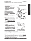
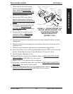
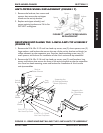
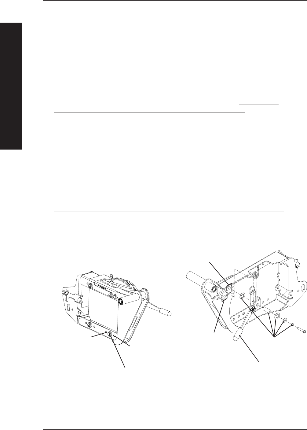
REPOSITIONING THE HEAVY DUTY GEARLESS/BRUSHLESS
MOTOR (FIGURE 14)
STANDARD POSITION - LENGTHENS the wheelbase and gives you the most stability
and standard maneuverability.
1-INCH FORWARD - CENTERS the wheelbase and gives you standard stability and
maneuverability.
2-INCH FORWARD - N/A
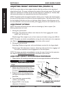
1. Determine the desired mounting position of the gearless/brushless motor.
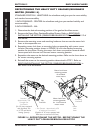
2. Remove the Heavy Duty Gearless/Brushless Motors. Refer to
REMOVING/
INSTALLING THE MOTOR (GEARLESS/BRUSHLESS MOTOR) in SECTION 12 of
this manual.
3. Remove the mounting screw and attaching hardware that secures the motor lock
lever to the suspension arm.
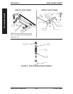
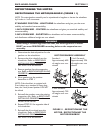
4. Reposition motor lock lever to mounting hole corresponding with motor mount
location. Mounting position shown in FIGURE 14 is for the standard mounting
position for the motor. Moving the motor lock lever one position forward would
correrspond with the one inch forward motor mounting position.
5. Reposition the motor to the desired mounting position. Refer to the chart above to
for motor mounting options.
6. Reinstall the motor to the mounting position determined in STEP 1. Refer to
REMOVING/INSTALLING THE MOTOR (GEARLESS/BRUSHLESS MOTOR) in
SECTION 12 of this manual.
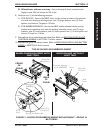
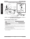
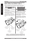
FIGURE 14 - REPOSITIONING THE MOTOR - REPOSITIONING THE
HEAVY DUTY GEARLESS/BRUSHLESS MOTOR
RWD WHEELCHAIRSSECTION 15
RWD WHEELCHAIRS
Not
Available
Standard -
Approximately 70%
of weight over
rear wheels
(For 3G chairs equipped
with High Back Van
or 2G Tilt and Recline
Seating Systems)
1-inch Forward - Approximately 65%
of weight over rear wheels
(Optional on 3G chairs equipped with
ASBA seats or Low Back Van Seat)
Motor
Lock
Lever
Attaching
Hardware
Motor Lock Lever
mounting position
for standard
motor mount
Motor Lock Lever
mounting position
for 1-inch forward
motor mount