


Part No. 1104849 103 3G Storm Series
®
Wheelchairs
ELECTRONICS
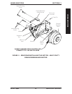
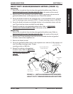
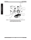
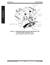
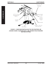
REMOVING GB CONTROLLER (WHEELCHAIRS EQUIPPED
WITH NON-POWERED SEATING SYSTEMS) (FIGURE 3)
1. Remove the battery boxes. Refer to REMOVING/INSTALLING THE BATTERY
BOXES in SECTION 9 of this manual.
2. Remove the controller shroud (if applicable).
3. Remove the 5/16-18 x 1-inch hex head cap screw that secures the controller
bracket and jumper cable to the base frame.
4. Remove the 5/16-18 x 1-inch hex head cap screw that secures the controller
bracket to the base frame.
5. Remove the 10-32 x 1/2-inch mounting screw and two (2) lockwashers that secure
the front of the GB controller and jumper cable to the controller bracket.
6. Remove the two (2) 10-32 x 1/2-inch mounting screws that secure the rear of the
GB controller to the controller bracket.
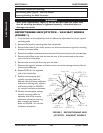
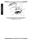
INSTALLING GB CONTROLLER (WHEELCHAIRS EQUIPPED
WITH NON-POWERED SEATING SYSTEMS) (FIGURE 3)
1. Secure the rear of the GB controller to the controller bracket with two (2) of the
NEW 10-32 x 1/2-inch mounting screws. Securely tighten.
2. Secure the front of the GB controller and one end of the jumper cable to the
controller bracket with one (1) of the NEW 10-32 x 1/2-inch mounting screw and
two (2) lockwashers. Securely tighten.
3. Secure one side of the controller bracket to the base frame as shown in FIGURE 3
with one (1) of the NEW 5/16-18 x 1-inch hex head cap screws. Securely tighten.
4. Secure the other side of the controller bracket and opposite end of jumper cable to
the base frame as shown in FIGURE 3 of the remaining NEW 5/16-18 x 1-inch hex
head cap screws. Securely tighten.
5. Reinstall the controller shroud (if applicable).
6. Reinstall the battery boxes. Refer to REMOVING/INSTALLING THE BATTERY
BOXES in SECTION 9 of this manual.
SECTION 13ELECTRONICS