


42
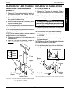
Footplate Depth Adjustment
1. Note the height of the footrest and the angle of the
footplate for reinstallation.
2. Loosen, but do not remove the two (2) allen screws
securing the footrest tubes to the wheelchair frame.
3. Remove the two (2) footrest tubes from the wheel-
chair frame.
4. Loosen, but do not remove the four (4) locknuts that
secure the footplate to the footrest tubes.
5. Remove the footrest tubes from the footrest.
6. Insert the footrest tubes into one (1) of two (2) depth
mounting positions to accommodate the user.
7. Adjust the angle of the footrest plate to the position
noted in STEP 1.
8. Tighten the four (4) locknuts that secure the footplate
to the footrest tubes.
9. Insert the footrest tubes into the wheelchair frame.
10. Adjust the footrest tubes to the height noted in STEP 1.
11. Tighten the two (2) allen screws to secure the foot-
rest tubes to the wheelchair frame.
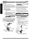
FOOTREST REPLACEMENT/
ADJUSTMENT (FIGURE 1)
WARNING
The position of the footrest, seat angle, back
angle, seating system/upholstery, caster size and
position, rear wheel size and position, anti-tippers,
as well as the user condition directly relate to the
stability of the wheelchair. Any change to one
(1) or any combination of the ten (10) may cause
the wheelchair to decrease in stability.
EXTREMEcare MUST be taken when changing the
stability of the wheelchair.
The footrest assembly MUST be at least 1-3/4-
inches above the ground/floor to avoid hitting
protruding objects when using this wheelchair.
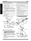
Replacing the Footrest
1. Loosen, but do not remove the two (2) allen screws
that secure the footrest to the wheelchair frame.
2. Slide the existing footrest tubes out of the wheel-
chair frame and install new footrest by reversing this
step.
3. Position the NEW footrest to a determined height.
4. Tighten the two (2) allen screws that secure the foot-
rest to the wheelchair frame.
5. Adjust the footplate to the desired position. Refer to
FOOTPLATE ANGLE ADJUSTMENT and/or
FOOTPLATE DEPTH ADJUSTMENT in this sec-
tion of the manual.
Footplate Angle Adjustment
1. Loosen, but do not remove the four (4) locknuts that
secure the footplate to the two (2) footrest tubes.
2. Position the footplate to the necessary angle to
accommodate the user.
3. Retighten the four (4) locknuts.
F
O
O
T
R
E
S
T
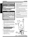
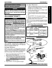
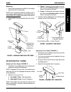
PROCEDURE 6 FOOTREST
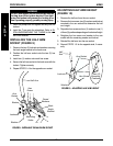
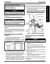
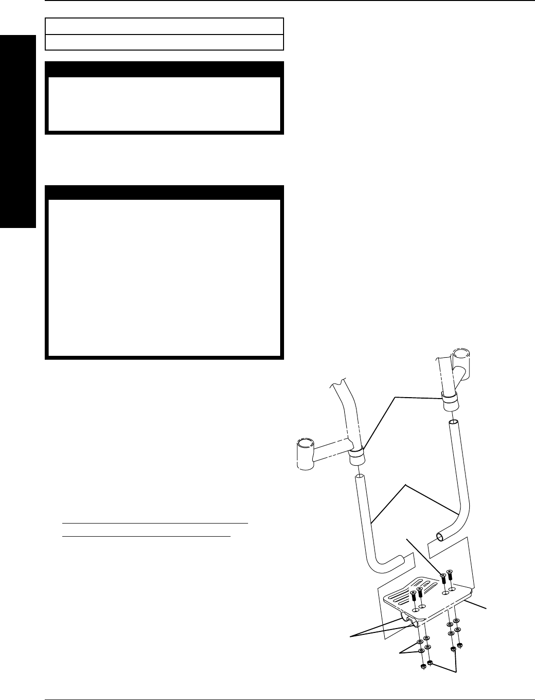
FIGURE 1 - FOOTREST REPLACEMENT/ADJUSTMENT
Allen
Screws
Footrest
Tubes
Flat
Screw
Footplate
This Procedure includes the following:
Footrest Replacement/Adjustment
WARNING
After ANY adjustments, repair or service and BE-
FORE use, make sure all attachment hardware is
tightened securely - otherwise, injury or damage
may result.
Washers
Locknuts
Depth
Mounting
Positions