


20
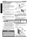
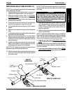
REPLACING TURNBUCKLE ASSEMBLY
- A-6/A6-S ONLY (FIGURE 5)
NOTE: The turnbuckle assembly consists of the inside
screw, turnbuckle, outside screw, flanges and rods. If
the turnbuckle assembly becomes disassembled, refer
to FIGURE 5.
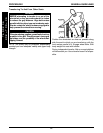
1. Carefully tip the wheelchair back so the back canes rest
on the ground.
2. Insert an allen wrench into the hole in the inside screw
and the hole in the rod to prevent the rod from spin-
ning.
3. Remove the two (2) hex screws securing the inside screw
to the seat crossmember.
4. Repeat STEPS 2-3 for the outside screw.
5. Remove the existing turnbuckle assembly from the seat
and frame crossmembers.
6. Rotate the NEW turnbuckle until an equal number
of threads shows on either end.
7. Position the NEW turnbuckle assembly with the jam nut
towards the seat crossmember as shown in FIGURE 5.
8. Position the inside screw between the tabs on the seat
crossmember.
9. Insert an allen wrench into the hole in the inside screw
and the hole in the rod to prevent the rod from spin-
ning.
10. Apply a removable thread locker to the threads of
one (1) hex screw.
11. Install the hex screw into one end of the inside screw to
secure the turnbuckle assembly to the seat crossmember.
12. Repeat STEPS 10-11 for opposite end of inside screw.
13. Repeat STEPS 8-12 to secure the outside screw to the
frame crossmember.
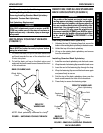
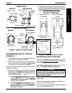
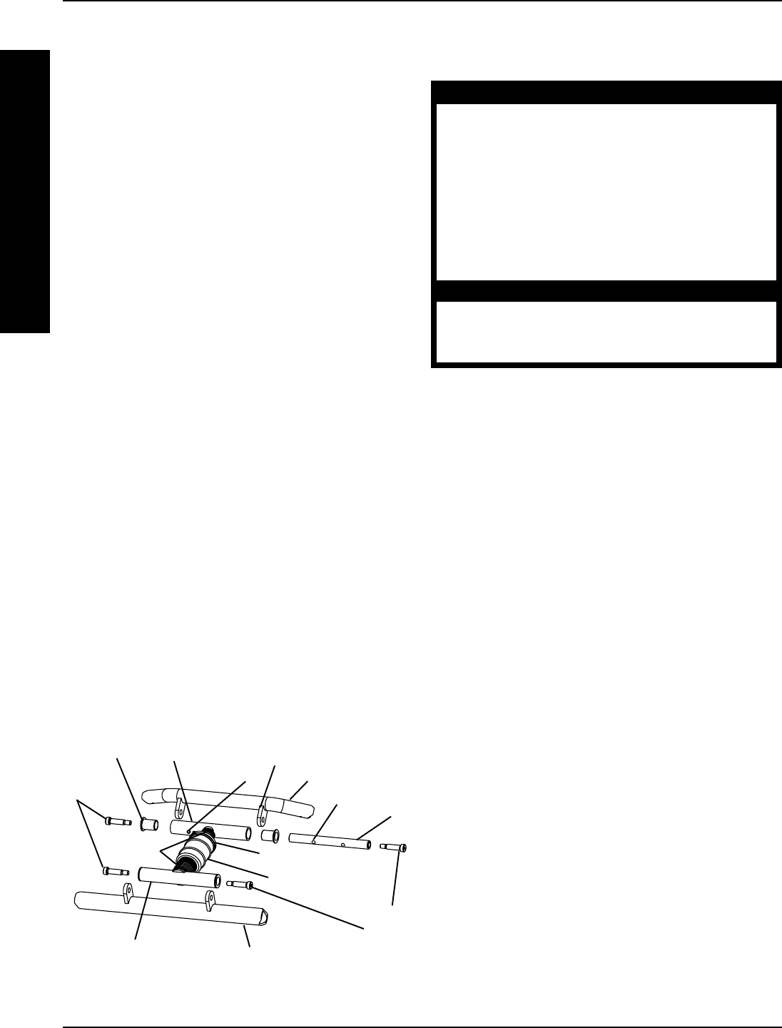
FIGURE 5 - REPLACING TURNBUCKLE ASSEMBLY -
A-6/A-6S ONLY
Inside Screw
Hole
Rod
Seat
Crossmember
Flange
Hex
Screws
Outside Screw
Frame Crossmember
Hex
Screws
Turnbuckle
Jam Nut
Threads
PROCEDURE 4 FRAME
F
R
A
M
E
Ta b
Hole
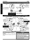
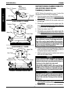
OPENING/CLOSING CLAMPS
(FIGURE 6)
WARNING
QUICK RELEASE LEVERS - Make sure the quick re-
lease levers are in the CLOSED position BEFORE
using the wheelchair, otherwise personal injury or
damage to the wheelchair may result.
STANDARD CAMBER OR RECEIVER TUBE CLAMPS
- Make sure the hex screws and locknuts are se-
curely tightened BEFORE using the wheelchair,
otherwise personal injury or damage to the
wheelchair may result.
CAUTION
DO NOT close the quick-release levers or tighten the
hex screws and locknuts without camber inserts in
the axle tube. Damage to the axle tube will occur.
Camber Clamps
1. Perform one (1) of the following to open a camber clamp:
A. QUICK RELEASE LEVERS - Pull the quick re-
lease lever to the open position.
B. STANDARD CAMBER CLAMPS - Loosen, but
do not remove the hex screw and locknut on the
camber clamp.
2. Perform one (1) of the following to close a camber clamp:
A. QUICK RELEASE LEVERS - Tighten the
threaded knob to secure the quick release lever.
Push the quick release lever on the camber
clamps to the closed position.
B. STANDARD CAMBER CLAMPS - Securely tighten
the hex screw and locknut to secure the axle tube.
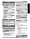
Receiver Tube Clamps
1. Perform one (1) of the following to open a receiver
tube clamp:
A. QUICK RELEASE LEVERS - Pull the quick re-
lease levers on the receiver tube clamps to the
open position.
B. STANDARD RECEIVER TUBE CLAMPS -
Loosen, but do not remove the hex screws and
locknuts on the receiver tube clamps.
2. Perfrom one (1) of the following to close a receiver
tube clamp:
A. QUICK RELEASE LEVERS - Tighten the
threaded knob to secure the quick release lever.
Push the quick release lever on the receiver tube
clamps to the closed position.
B. STANDARD RECEIVER TUBE CLAMPS -
Tighten the hex screw and locknut on the re-
ceiver tube clamp. Torque to 75 in./lbs.