


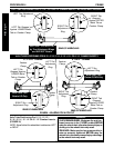
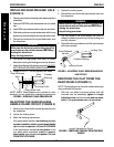
26
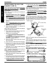
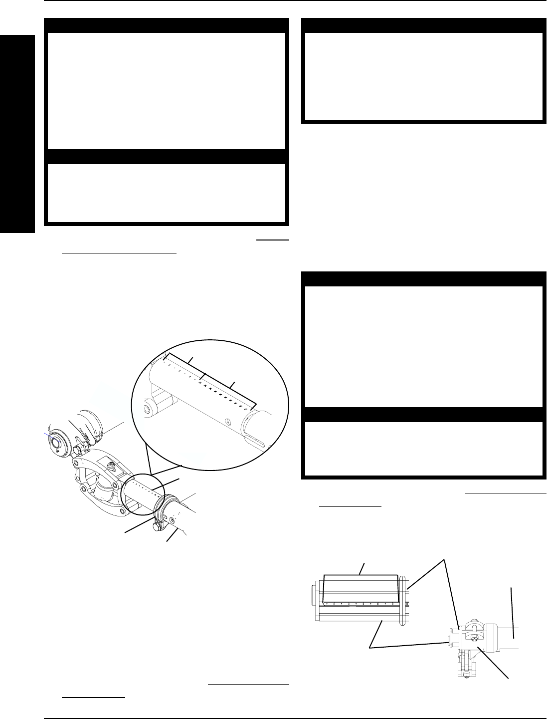
Indexing Marks
Axle Tube
Camber Insert
Indexing Ring
Camber
Clamp
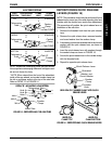
FIGURE 12 - ADJUSTING WHEELBASE WIDTH
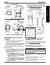
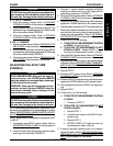
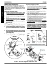
PROCEDURE 4 FRAME
F
R
A
M
E
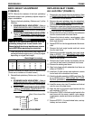
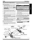
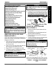
FIGURE 11 - ADJUSTING WHEELBASE LENGTH
(ADJUSTING CENTER OF GRAVITY)
Receiver Tube
Receiver
Tube Clamp
DETAIL "A" -
TELESCOPING
TUBE MARKS
"X" Marks
"0" Marks
Telescoping
Tube
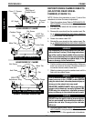
WARNING
QUICK RELEASE LEVERS - Make sure the quick re-
lease levers are in the CLOSED position BEFORE
using the wheelchair, otherwise injury or damage
to the wheelchair may result.
STANDARD RECEIVER TUBE CLAMPS - Make sure
the hex screws and locknuts are securely tight-
ened BEFORE using the wheelchair, otherwise in-
jury or damage to the wheelchair may result.
CAUTION
DO NOT close the quick-release levers or tighten
the hex screws and locknuts without telescoping
tubes in the receiver tubes. Damage to the re-
ceiver tubes will occur.
3. Close both receiver tube clamps. Refer to
OPEN-
ING/CLOSING CLAMPS in this procedure of the
manual.
4. Test the occupied wheelchair for a short distance to
make sure there is no excessive drag to either side.
NOTE: If drag to either side occurs, refer to DETERMIN-
ING TOE IN/TOE OUT in this section of the manual.
WARNING
NEVER position the camber inserts in the axle tube
with more than 3-inches (12 indexing marks show-
ing) of the camber insert outside of the axle tube.
The camber inserts will not be securely tightened
in the axle tube resulting in possible injury to the
user or damage to the wheelchair.
2. Position the camber insert to the desired position.
Make sure there is no more than 3-inches (12 index-
ing marks showing) of the camber inserts outside of
the axle tube.
3. Slide the indexing ring on the camber insert until it is
flush with the frame bracket.
NOTE: Before using the wheelchair, make sure both cam-
ber inserts are set at the same indexing mark. This will
make sure the distance between the rear wheel and the
wheelchair is the same on both sides.
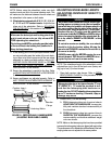
WARNING
QUICK RELEASE LEVERS - Make sure the quick re-
lease levers are in the CLOSED position BEFORE
using the wheelchair, otherwise personal injury or
damage to the wheelchair may result.
STANDARD CAMBER CLAMPS - Make sure the hex
screws and locknuts are securely tightened BE-
FORE using the wheelchair, otherwise personal
injury or damage to the wheelchair may result.
CAUTION
DO NOT close the quick-release levers or tighten
the hex screws and locknuts without camber in-
serts in the axle tube. Damage to the axle tube
will occur.
4. Close the camber clamp. Refer to
OPENING/CLOS-
ING CLAMPS in this procedure of the manual.
5. Repeat STEPS 1-4 for the opposite side of the wheel-
chair.
ADJUSTING WHEELBASE WIDTH
(FIGURE 12)
NOTE: Perform this procedure on one (1) side of the
wheelchair at a time for ease of adjustment.
1. Open the camber clamp. Refer to OPENING/CLOS-
ING CLAMPS in this procedure of the manual.