


22
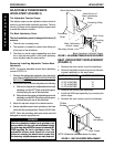
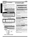
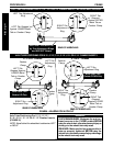
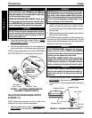
AXLE TUBE POSITIONING FOR 0°/3°, 0°/6°, 3°/6° OR 9°/12° CAMBER INSERTS - NO ADJUSTMENT REQUIRED
LEFT Tab Stopped
Against LOWER Metal
Tab on Camber Clamp
LEFT Toe Adjustment
Ring
Axle Tube - LOCKED OUT
by Toe Adjustment Rings
and Will NOT Rotate
RIGHT Tab
Stopped
Against UPPER
Metal Tab on
Camber Clamp
RIGHT Toe
Adjustment
Ring
FIGURE 8 - ADJUSTING TOE IN/TOE OUT
REAR OF WHEELCHAIR
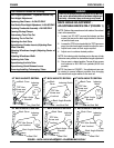
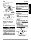
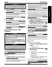
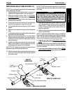
AXLE TUBE POSITIONING FOR 0°/9°, 0°/12°, 3°/9°, 3°/12°,
6°/9° OR 6°/12° CAMBER INSERTS
0°, 3° OR 6° CAMBER 9° OR 12° CAMBER
Camber
Clamp
LEFT Toe
Adjustment Ring
Axle Tube - Will
Rotate DOWN Only
Camber
Clamp
RIGHT Toe
Adjustment Ring
Axle Tube - Will
Rotate UP Only
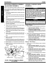
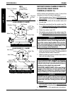
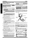
LEFT Toe
Adjustment
Ring
Camber
Clamp
Camber
Clamp
RIGHT Toe
Adjustment
Ring
LEFT Tab
Stopped Against
LOWER Metal
Tab on Camber
Clamp
RIGHT Tab
Stopped
Against UPPER
Metal Tab on
Camber Clamp
REAR OF WHEELCHAIR
REAR OF WHEELCHAIR
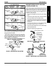
Axle Tube Positioning For 0°/9°, 0°/12°,
3°/9°, 6°/9°
, 3°/12° Or 6°/12° Camber Inserts
(FIGURE 8)
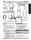
NOTE: Stand behind the wheelchair to determine LEFT
or RIGHT.
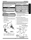
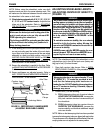
WARNING
QUICK RELEASE LEVERS - Make sure the quick re-
lease levers are in the CLOSED position BEFORE
using the wheelchair, otherwise personal injury or
damage to the wheelchair may result.
STANDARD - Make sure the hex screws and lock-
nuts are securely tightened BEFORE using the
wheelchair, otherwise personal injury or damage
to the wheelchair may result.
PROCEDURE 4 FRAME
F
R
A
M
E