25
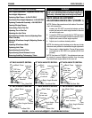
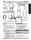
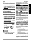
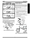
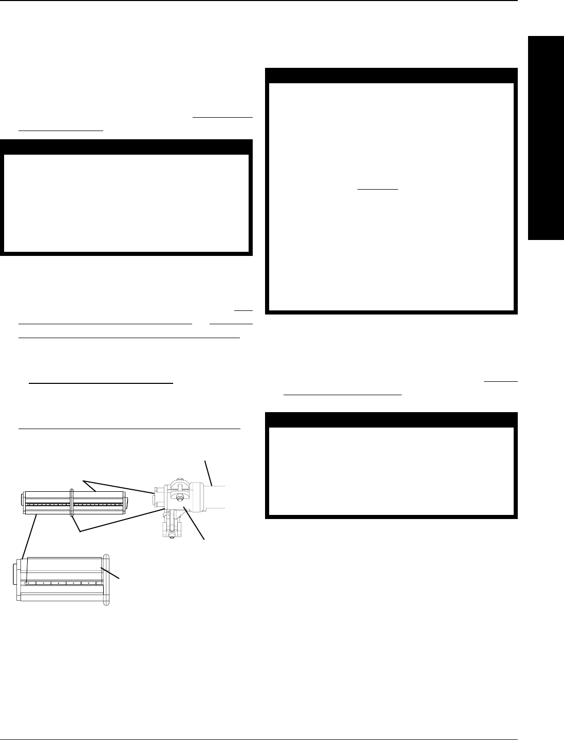
Camber Insert -
Rotate 180°
Indexing Ring
Axle Tube
Camber
Clamp
Indexing Marks
F
R
A
M
E
PROCEDURE 4FRAME
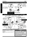
FIGURE 10 - REPOSITIONING CAMBER INSERTS
(ADJUSTING REAR WHEEL CAMBER)
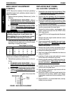
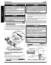
NOTE: Before using the wheelchair, make sure both
camber inserts are set to the same indexing mark. This
will make sure the distance between the rear wheel and
the wheelchair is the same on both sides.
10. Wheelchairs equipped with 0°/9°, 0°/12°, 3°/9°, 6°/
9°
, 3°/12° or 6°/12° camber inserts - Adjust the toe
in/toe out of the wheelchair. Refer to ADJUSTING
TOE IN TOE OUT in this section of the manual.
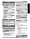
WARNING
Make sure the detent pin and locking pins of the
quick/quad-release axle are fully released BE-
FORE operating the wheelchair.
The locking pins MUST be protruding past the inside
of the rear wheel axle bushing for a positive lock.
Keep locking pins clean.
11. If the locking pins of the quick/quad-release axles
are not protruding past the inside of the axle bush-
ing or there is too much movement of the rear wheel
assembly in a back and forth position, refer to
AD-
JUSTING QUICK-RELEASE AXLES or REMOV-
ING THE PLAY FROM THE REAR WHEELS in
PROCEDURE 5 of this manual.
12. Ensure the wheelchair is parallel to the floor. Refer
to
ADJUSTING CASTER HEIGHT in PROCEDURE
5 of the manual.
13. Ensure anti-tippers are adjusted properly. Refer to
ANTI-TIPPER ADJUSTMENT/REPLACEMENT in
PROCEDURE 7 of this manual.
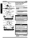
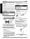
ADJUSTING WHEELBASE LENGTH
(ADJUSTING CENTER OF GRAVITY)
(FIGURE 11)
WARNING
The position of the footrest, seat angle, back angle,
seating system/upholstery, caster size and position,
rear wheel size and position, anti-tippers, as well as
the user condition directly relate to the stability of
the wheelchair. Any change to one (1) or any com-
bination of the ten (10) may cause the wheelchair
to decrease in stability. EXTREMEcare MUST be taken
when changing the stability of the wheelchair. Re-
fer to the chart in
STABILITY in PROCEDURE 1 of this
manual.
To maintain maximum stability, the rear wheels
should be left in the factory setting. Moving the
rear wheels FORWARD causes the wheelchair to
decrease in stability.
ALWAYS ensure stability BEFORE moving the rear
wheels forward. TEST wheelchair BEFORE it is oc-
cupied by the end user to ensure safety.
NOTE: The wheelbase length of the wheelchair can be
adjusted from just in front of the back cane (factory set-
ting) up to four (4) inches forward.
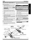
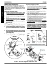
1. Open both receiver tube clamps. Refer to OPEN-
ING/CLOSING CLAMPS in this procedure of the
manual.
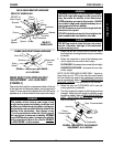
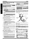
WARNING
Telescoping tubes have two types of marks - "0" and
"X" (DETAIL "A"). "X" marks are provided to indi-
cate that the telescoping tube has been ex-
tended too far. DO NOT adjust the telescoping tubes
so an "X" marks are showing. Otherwise, injury or
damage may occur.
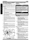
2. Perform one (1) of the following:
A. PULL telescoping tubes out of receiver tubes to
LENGTHEN THE WHEELBASE, increase sta-
bility and maintain standard maneuverability of
the wheelchair.
B. PUSH telescoping tubes into receiver tubes to
SHORTEN THE WHEELBASE, increase the
maneuverability and distribute additional weight
onto rear wheels.
NOTE: Marks on the telescoping tube have been provided
to ensure the telescoping tubes are aligned with each other.
The performance of the wheelchair will be affected if the tele-
scoping tubes are not adjusted to the same position.


