


47
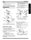
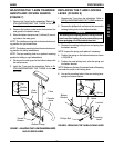
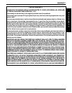
ADJUSTING THE T-ARM TRANSFER
ASSISTS AND/OR SIDE GUARDS
(FIGURE 7)
1. Remove the T-arm from the wheelchair. Refer to IN-
STALLING/REMOVING THE T-ARMS in this sec-
tion of the manual.
2. Remove the bottom socket screw that secures the
side guard to the bottom clamp.
3. Move the bottom clamp to one (1) of three (3) mount-
ing holes in the side guard.
NOTE: The middle mounting hole is the standard mount-
ing position for rigid wheelchairs.
NOTE: The bottom mounting hole is the standard mount-
ing position for folding wheelchairs.
NOTE: The top mounting hole is an optional mounting
position for folding or rigid wheelchairs.
4. Re-secure the side guard to the bottom clamp with
the socket screw.
5. Install the T-arm onto the wheelchair. Refer to
IN-
STALLING/REMOVING THE T-ARMS in this sec-
tion of the manual.
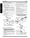
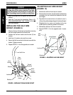
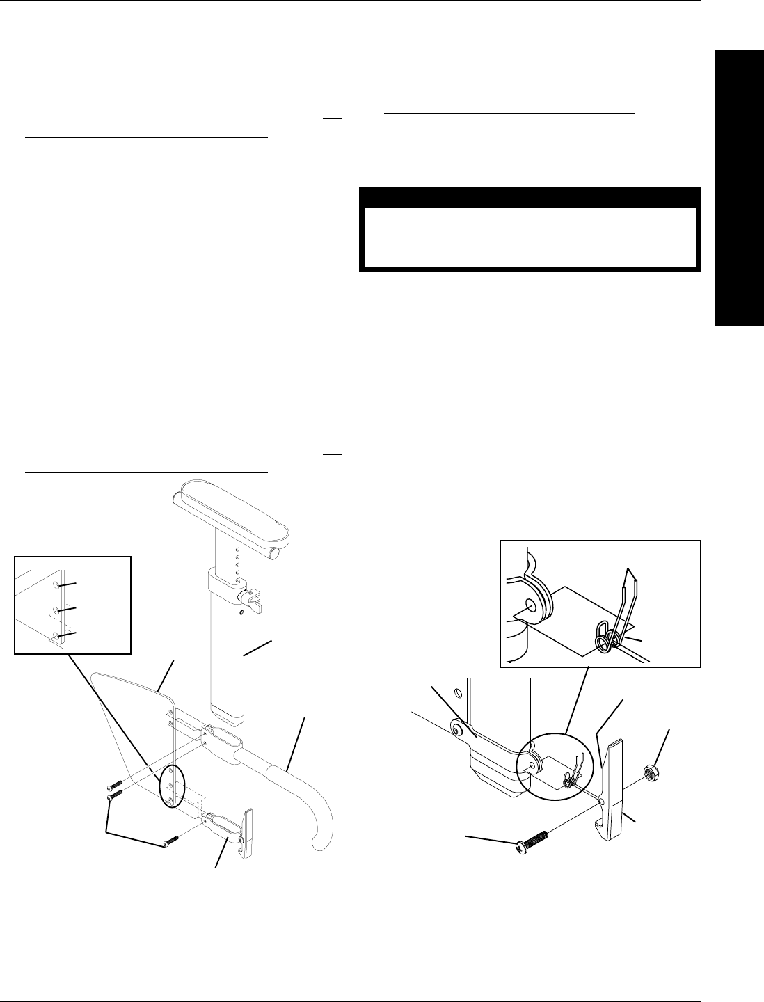
REPLACING THE T-ARM LOCKING
LEVER (FIGURE 8)
1. Remove the T-arm from the wheelchair. Refer to
INSTALLING/REMOVING THE T-ARMS in this sec-
tion of the manual.
2. Remove the phillips bolt and locknut that secure the
existing locking lever to the bottom bracket.
CAUTION
The locking lever is spring loaded. Place your free
hand over the locking lever to prevent the parts
from springing off of the bottom bracket.
3. Remove the existing locking lever and spring from
the bottom bracket.
NOTE: Inspect the spring and replace if necessary.
4. Position the spring on the bottom bracket as shown
in FIGURE 8.
5. Position the new locking lever onto the spring and
the bottom bracket.
NOTE: Make sure the two (2) extended ends of the spring
are inside the notch in the locking lever.
6. Line up the mounting holes in the new locking lever,
spring and bottom bracket.
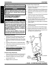
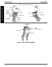
FIGURE 7 - ADJUSTING THE T-ARM TRANSFER ASSISTS
AND/OR SIDE GUARDS
Bottom
Bracket
Locking
Lever
Spring
Extended Ends
Locknut
Notch
Phillips Bolt
FIGURE 8 - REPLACING THE T-ARM LOCKING LEVER
A
R
M
S
Socket
Screws
Bottom Clamp
Transfer
Assist
Top
Middle
Bottom
Side
Guard
T-Arm
PROCEDURE 8ARMS