


36
PROCEDURE 5 WHEELS
W
H
E
E
L
S
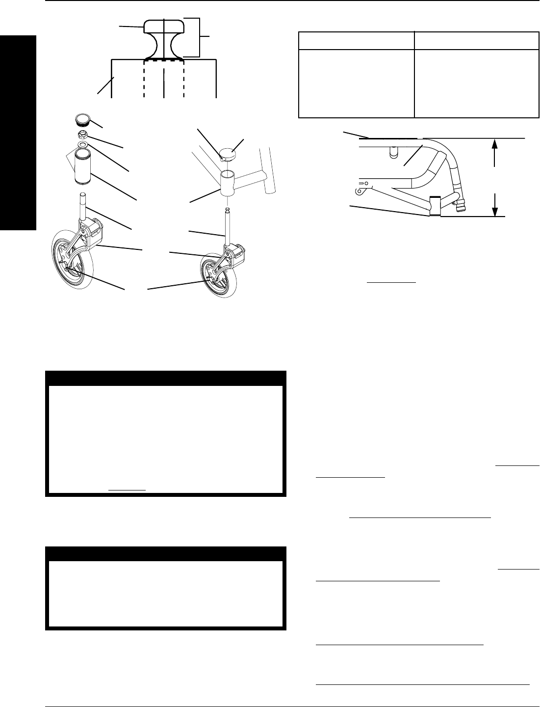
Front Seat-to-floor Height Adjustment
NOTE: Refer to STABILITY in PROCEDURE 1 for warn-
ings concerning wheelchair stability.
Seat-to-floor height is determined by measuring from the
top of the seat rail to the ground/floor.
The different seat-to-floor heights are possible by using
different combinations of caster size, caster position, and
axle tube position.
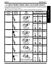
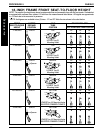
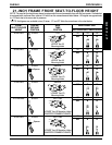
1. Refer to the charts on the following pages to deter-
mine available front seat-to-floor heights for each
wheelchair frame size.
2. Determine the changes needed to the casters, axle
tube and anti-tippers by reading across the chart for
the seat-to-floor height determined in STEP 1.
3. After determining the caster size, refer to
REPLAC-
ING CASTERS in this procedure of the manual to
replace the casters or adjust the caster position.
4. After replacing or adjusting the caster size/position,
refer to
ADJUSTING CASTER HEIGHT in this pro-
cedure of the manual to add/remove fork spacers
and add/remove washers to ensure caster
headtubes are perpendicular to the ground.
5. After adjusting the caster height, refer to REPOSI-
TIONING THE AXLE TUBE in PROCEDURE 4 of
the manual to adjust the axle tube position.
6. Anti-tipper height (if applicable) must be adjusted to
maintain 1-1/2 to 2-inch clearance between the bot-
tom of the anti-tipper wheels and the floor. Refer to
ADJUSTING ANTI-TIPPER HEIGHT in PROCE-
DURE 7 of this manual.
7. Ensure wheellocks engage properly. Refer to
WHEEL LOCK ADJUSTMENT/REPLACEMENT in
this procedure of the manual.
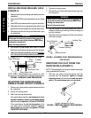
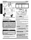
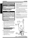
FIGURE 12 - DETERMINING FRAME SIZE
Seat
Upholstery
Seat Rail
Bottom of
Caster
Headtube
LENGTH
(INCHES)
ADJUSTING FRONT
SEAT-TO-FLOOR HEIGHT
WARNING
The position of the footrest, seat angle, back angle,
seating system/upholstery, caster size and position,
rear wheel size and position, anti-tippers, as well as
the user condition directly relate to the stability of the
wheelchair. Any change to one (1) or any combi-
nation of the ten (10) may cause the wheelchair to
decrease in stability. EXTREME care MUST be taken
when changing the stability of the wheelchair. Refer
tothe chart in
STABILITY in PROCEDURE 1 of this manual.
NOTE: Each wheelchair frame has been designed for a
specific size rear wheel. Invacare does not recommend
changing rear wheel size.
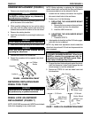
WARNING
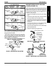
Forks for quick release casters are available in
different sizes to accommodate spacers. If the
wheelchair is equipped with quick release cast-
ers, DO NOT adjust front seat-to-floor height with-
out changing forks.
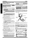
Determining Frame Size (FIGURE 12)
1. To determine frame size, measure from the bottom of
the caster headtube to the top of the seat rail at the
edge of the seat upholstery.
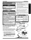
Bolt
Dust Cover
Locknut
Detent
Pin
Quick- Release
Caster
Headtube Cap
Fork
Fork Stem
Spacer
Headtube
Approximately
1/4-inch
Quick-Release
Caster Fork
Stem
Caster
Headtube
FIGURE 11 - INSTALLING QUICK-RELEASE CASTERS
2. Refer to the chart to determine the frame size.
LENGTH (INCHES) FRAME SIZE
9.86 17
10.86 18
11.86 19
12.86 20
13.86 21