


32
PROCEDURE 5 WHEELS
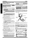
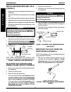
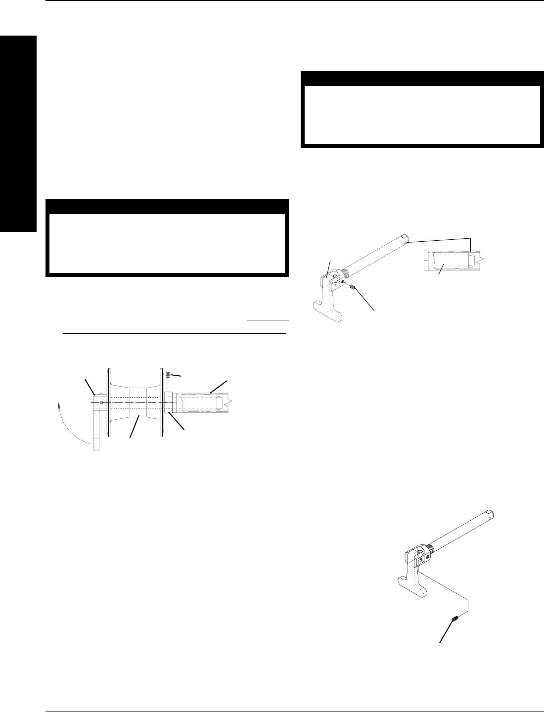
Length Adjustment Screw
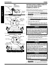
FIGURE 5 - REMOVING THE PLAY FROM THE REAR
WHEELS
REMOVING THE PLAY FROM THE
REAR WHEELS (FIGURE 5)
NOTE: The adjusting nut on the quick-release axles origi-
nally performed this function.
1. With the rear wheel and quad-release axle still
mounted onto the wheelchair, tighten the length
adjusting screw until there is no in and out move-
ment of the quad-release axle and rear wheel.
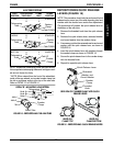
Allen
Screw
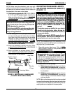
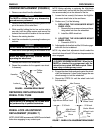
INSTALLING QUAD-RELEASE AXLE
(FIGURE 3)
1. Remove rear wheel and existing quick-release axle from
wheelchair.
2. Remove EXISTING quick-release axle from rear wheel
hub.
3. Insert NEW quad-release axle through rear wheel hub.
4. Slide locking collar onto quad-release axle until it is snug
against rear wheel and tighten securely with allen screw.
5. Reinstall rear wheel and the quad-release axle onto
the wheelchair.
WARNING
Make sure the detent pin and locking pins of the
quad-release axle are fully released BEFORE op-
erating the wheelchair.
Keep locking pins clean.
6. Flip handle of quad-release axle down to release
detent pin ensuring that locking pins are fully released.
7. If detent pin does not fully release, proceed to
ADJUST-
ING THE QUAD-RELEASE HANDLE IN AND/OR OUT.
8. Repeat STEPS 1-7 for the opposite rear wheel.
Quad-Release
Axle
Rear Wheel Hub
Locking Collar
Camber
Bushing
FIGURE 3 - INSTALLING QUAD-RELEASE AXLE
NOTE: End of Quad-Release axle is shown for refer-
ence only. It is not visible when inserted into camber bar.
W
H
E
E
L
S
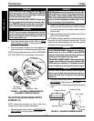
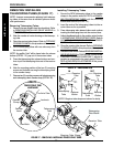
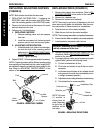
Quad-Release
Handle
Locking Screw
Locking Pins
Camber Bushing
FIGURE 4 - ADJUSTING QUAD- RELEASE HANDLE IN/
AND OR OUT
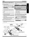
ADJUSTING THE QUAD-RELEASE
HANDLE IN AND/OR OUT (FIGURE 4)
1. Remove rear wheel and the quad-release axle from
the wheelchair.
2. Loosen the locking screw.
3. Make the following adjustments:
If the quad-release handle is not releasing the lock-
ing pins completely, rotate the quad-release handle
approximately one-quarter (1/4) turn CLOCKWISE.
If the quad-release handle hits the spokes of the
rear wheel when assembled, rotate the quad-re-
lease handle approximately one-quarter (1/4) turn
COUNTERCLOCKWISE.
4. Tighten the locking screw.
5. Reinstall the rear wheel and quad-release axle onto
the wheelchair.
WARNING
Make sure the detent pin and locking pins of the
quad-release axle are fully released BEFORE op-
erating the wheelchair.
Keep locking pins clean.
6. Flip the handle of the quad-release axle down to
release the detent pin ensuring that the locking pins
are fully released.
7. Repeat the above procedures until the quad-release
axle locks correctly.