


21
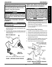
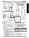
Closed
Position
Open Position
Quick
Release
Lever
Camber Clamp
Hex Screw
Locknut
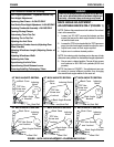
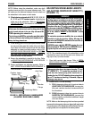
STANDARD QUICK RELEASE
Camber Clamp
CAMBER CLAMPS
STANDARD QUICK RELEASE
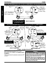
Locknut
Bolt
Open
Position
Closed
Position
Quick Release
Lever
Receiver
Tube Clamp
Receiver
Tube Clamp
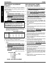
RECEIVER TUBE CLAMPS
FIGURE 6 - OPENING/CLOSING CLAMPS
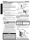
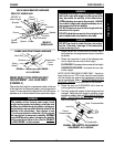
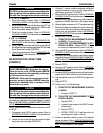
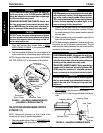
DETERMINING TOE IN/TOE OUT
(FIGURE 7)
1. Inflate all pneumatic tires to recommended tire pres-
sures (listed on the sidewall of the tire).
2. Measure the distance between the centerlines at the
rear and front of the rear wheels at approximately
12-inches from the ground/floor (FIGURE 7).
NOTE: For optimum accuracy, perform STEP 2 with the
wheelchair occupied.
3. Determine the difference between the two (2) mea-
surements. If the difference between the two (2)
measurements is NOT within
+1/8-inch, one (1) of
two (2) conditions exists:
A. If the back centerline measurement of the rear
wheels is SMALLER than the front centerline
measurement of the rear wheels, a TOE-OUT
condition exists (FIGURE 7).
B. If the back centerline measurement of the rear
wheels is LARGER than the front centerline
measurement of the rear wheels, a TOE-IN con-
dition exists (FIGURE 7).
Toe-in
Smaller Than
Front
Larger Than Front
Toe-out
Front of Wheelchair
TOP VIEW OF WHEELCHAIR
Rear Centerline of
Wheelchair
Front Centerline of
Wheelchair
12-inches
FIGURE 7 - DETERMINING TOE IN/TOE OUT
DETAIL "A" - SIDE VIEW
OF WHEELCHAIR
4. If the difference between the measurements is not
within
+1/8-inch, correct the toe-in/toe-out condition.
Refer to
ADJUSTING TOE-IN/TOE-OUT in this pro-
cedure of the manual.
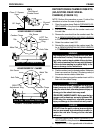
ADJUSTING TOE IN/TOE OUT
NOTE: If the axle tube has been repositioned or replaced,
proceed to LOCKING OUT AXLE TUBE in this proce-
dure of the manual.
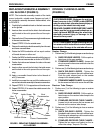
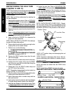
Axle Tube Positioning For 0°/3°, 0°/6°, 3°/6°
or 9°/12° Camber Inserts (FIGURE 8)
CAUTION
DO NOT rotate the axle tube if the axle tube is
locked out by the toe adjustment rings. If a locked
out axle tube is rotated, damage to the toe ad-
justment rings will occur.
NOTE: Refer to FIGURE 8 for a description of a locked
out axle tube.
There is NO adjustment required to maintain a cor-
rect toe in/toe out measurement.
NOTE: The axle tube will be locked out by the toe adjust-
ment rings and will NOT rotate.
PROCEDURE 4FRAME
F
R
A
M
E
Threaded Knob
Threaded
Knob