


18
PROCEDURE 4 FRAME
BACK HEIGHT ADJUSTMENT
(FIGURE 2)
NOTE: Observe the tautness of the back upholstery/
adjustable tension back upholstery adjuster straps for
proper reinstallation.
1. Remove the back upholstery. Perform one (1) of the
following:
A. STANDARD BACK UPHOLSTERY - Refer to
REMOVING/INSTALLING STANDARD BACK
UPHOLSTERY in PROCEDURE 3 of the manual.
B. ADJUSTABLE TENSION BACK UPHOLSTERY
- Refer to
ADJUSTABLE TENSION BACK UP-
HOLSTERY in PROCEDURE 3 of the manual.
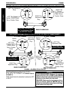
WARNING
Push pin of the back cane insert bar MUST be
protruding through hole in each back cane.
Ensure that both back cane insert bars are at same
height BEFORE reassembling the wheelchair.
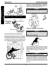
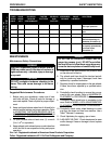
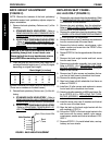
2. Press the push pin on the back cane insert bar IN
and adjust the back height to one (1) of five (5) heights
depending on original back height:
Back Height (in inches)
✪ ✪
✪ ✪
✪ HOLE # 8-11 10-14 12-16 14-18 16-20
1 8 10121416
2 9 11131517
3 10 12 14 16 18
4 11 13 15 17 19
5 N/A 14 16 18 20
✪ Holes numbered from bottom to top for reference only.
(There are no numbers on the back canes.)
3. Reinstall back upholstery. Perform one (1) of the fol-
lowing:
A. STANDARD BACK UPHOLSTERY - Refer to
REMOVING/INSTALLING STANDARD BACK
UPHOLSTERY in PROCEDURE 3 of the manual.
B. ADJUSTABLE TENSION BACK UPHOLSTERY
- Refer to
ADJUSTABLE TENSION BACK UP-
HOLSTERY in PROCEDURE 3 of this manual.
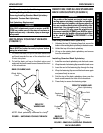
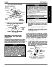
FIGURE 2 - BACK HEIGHT ADJUSTMENT
Back
Cane
F
R
A
M
E
Hole Number
5
4
3
2
1
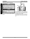
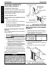
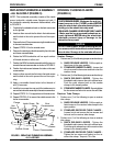
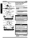
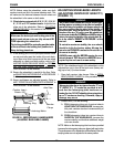
REPLACING SEAT FRAME -
A-6/A-6S ONLY (FIGURE 3)
1. Remove the rear wheels from the wheelchair. Refer
to
REMOVING/INSTALLING REAR WHEELS in
PROCEDURE 5 of the manual.
2. Remove the seat upholstery from the wheelchair.
Refer to
SEAT UPHOLSTERY REPLACEMENT in
PROCEDURE 3 of the manual.
3. Remove the wheel locks from the wheelchair. Refer
to
WHEEL LOCK ADJUSTMENT/REPLACEMENT
in PROCEDURE 5 of this manual.
4. Remove the locknut, two (2) washers, stop and screw
from the rearmost end of the seat frame.
5. Remove the locknut washer, coved spacer, nylon
spacer, washer and screw from the FRONT of the
back angle bracket.
6. Repeat STEPS 4-5 for the opposite side of the wheel-
chair.
7. Remove the back angle bracket and back canes
from the seat frame.
8. Disconnect turnbuckle assembly from seat frame.
Refer to STEPS 1-3 in
REPLACING THE TURN-
BUCKLE ASSEMBLY - A6/A-6S ONLY in this pro-
cedure of the manual.
9. Remove two (2) allen screws and washers that se-
cure front of seat frame to wheelchair front frame.
10. Remove the existing seat frame.
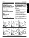
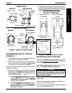
11. Align front of seat rail with wheelchair front frame as
shown in FIGURE 3.
12. Install two (2) allen screws and washers to secure
front of seat rail to wheelchair front frame.
13. Attach turnbuckle assembly to NEW seat frame. Re-
fer to STEPS 8-12 in
REPLACING THE TURN-
BUCKLE ASSEMBLY - A-6/A-6S ONLY in this pro-
cedure of the manual.
14. Install the screw, stop, two (2) washers and locknut
onto the rear of the seat frame.
15. Align the latch on the back angle bracket with the
stop installed in STEP 14.
16. Secure the FRONT of the back angle bracket to the
seat frame with the screw, washer, nylon spacer,
coved spacer, washer and locknut as shown in FIG-
URE 3.
17. Reverse STEPS 1-3 to install wheel locks, seat up-
holstery and rear wheels.
Back Cane Insert Bar