


23
FRAME PROCEDURE 4
F
R
A
M
E
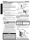
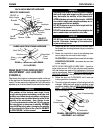
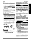
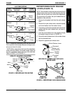
3. Using an "L" square, rotate the axle tube until the flat
edge of the camber insert is at a 90° angle with the
ground/floor as shown in FIGURE 9.
4. Close the RIGHT camber clamp. Refer to
OPENING/
CLOSING CLAMPS in this procedure of the manual.
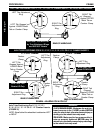
5. Rotate the LEFT toe adjustment ring until the tab stops
against the LOWER metal tab on the camber clamp.
6. Securely tighten set screw on LEFT toe adjustment ring.
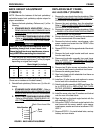
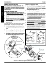
7. Measure the distance between the center lines at the
rear and front of the rear wheels at approximately 12-
inches from the ground/floor. Refer to
DETERMIN-
ING TOE IN/TOE OUT in this procedure of the manual.
8. Perform one (1) of the following:
A. TOE IN/TOE OUT MEASUREMENT IS WITHIN
±1/8-INCH - Proceed to step 8.
B. TOE IN/TOE OUT MEASUREMENT IS
NOT
WITHIN ±1/8-INCH - Repeat STEPS 1-7 until
toe in/toe out measurement is within ±1/8 inch.
9. Open the RIGHT camber clamp. Refer to
OPENING/
CLOSING CLAMPS in this procedure of the manual.
10. Reposition the camber inserts to the highest degree
of camber. Refer to
REPOSITIONING CAMBER IN-
SERTS (ADJUSTING REAR WHEEL CAMBER) in
this procedure of the manual.
11. Repeat STEP 3.
12. Close the LEFT camber clamp. Refer to
OPENING/
CLOSING CLAMPS in this procedure of the manual.
13. Rotate the RIGHT toe adjustment ring until the tab stops
against the UPPER metal tab on the camber clamp.
14. Securely tighten set screw on RIGHT toe adjustment
ring.
15. Repeat STEP 7.
16. Perform one (1) of the following:
A. TOE IN/TOE OUT MEASUREMENT IS WITHIN
±1/8-INCH -
1. Proceed to STEP 17.
B. TOE IN/TOE OUT MEASUREMENT IS
NOT
WITHIN ±1/8-INCH -
1. Repeat STEP 1.
2. Loosen the set screw on the RIGHT toe ad-
justment ring.
3. Repeat STEP 3.
4. REPEAT STEPS 12-16 until toe in/toe out
measurement is within ±1/8 inch.
17. If desired, reposition camber inserts to the desired
degree of camber. Refer to
REPOSITIONING CAM-
BER INSERTS (ADJUSTING REAR WHEEL CAM-
BER) in this procedure of the manual.
CAUTION
DO NOT close the quick-release levers or tighten the
hex screws and locknuts without camber inserts in
the axle tube. Damage to the axle tube will occur.
0°, 3° OR 6° CAMBER.
1. Open the camber clamps. Refer to
OPENING/
CLOSING CLAMPS in this procedure of the manual.
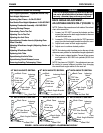
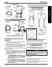
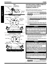
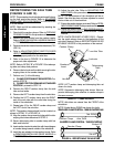
2. Slowly rotate the axle tube until the tab on the LEFT toe
adjustment ring is stopped against the LOWER metal
tab on the camber clamp (FIGURE 8).
3. Close the camber clamps. Refer to
OPENING/
CLOSING CLAMPS in this procedure of the manual.
9° OR 12° CAMBER.
1. Open the camber clamps. Refer to
OPENING/CLOS-
ING CLAMPS in this procedure of the manual.
2. Slowly rotate the axle tube until the tab on the RIGHT
toe adjustment ring is stopped against the UPPER metal
tab on the camber clamp (FIGURE 8).
3. Close the camber clamps. Refer to
OPENING/CLOS-
ING CLAMPS in this procedure of the manual.
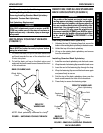
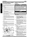
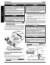
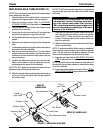
ADJUSTING THE AXLE TUBE
(FIGURE 9)
WARNING
QUICK RELEASE LEVERS - Make sure the quick re-
lease levers are in the CLOSED position BEFORE
using the wheelchair, otherwise injury or damage
to the wheelchair may result.
STANDARD - Make sure the hex screws and lock-
nuts are securely tightened BEFORE using the
wheelchair, otherwise injury or damage to the
wheelchair may result.
CAUTION
DO NOT close the quick-release levers or tighten the
hex screws and locknuts without camber inserts in
the axle tube. Damage to the axle tube will occur.
NOTE: Before performing this procedure, make sure the cam-
ber inserts are positioned to the lowest degree of camber.
Refer to
REPOSITIONING CAMBER INSERTS (ADJUST-
ING REAR WHEEL CAMBER) in this section of the manual.
NOTE: Stand behind the wheelchair to determine LEFT
or RIGHT.
1. If necessary, open BOTH camber clamps. Refer to
OPENING/CLOSING CLAMPS in this procedure of
the manual.
2. Loosen the set screw that secures each toe adjust-
ment ring to the axle tube (FIGURE 9).