


29
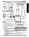
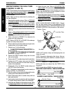
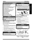
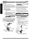
PROCEDURE 4FRAME
AXLE TELESCOPING CLAMP CLAMP
POSITION TUBE HOLE HOLE POSITION*
TOP A 1 STANDARD
B2
MIDDLE B 1 STANDARD
C2
BOTTOM A 2 INVERTED
B1
NOTE: Suspension telescoping tubes and tabs shown.
Non-suspension telescoping tubes and anti-tipper sock-
ets are not shown for clarity.
* NOTE: When viewed from the front of the wheelchair,
inside of the rear wheels, an inverted camber clamp has
the tab or anti-tipper socket at the top of the axle tube.
Refer to DETAIL "A" of FIGURE 14.
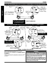
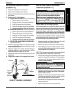
Telescoping Tube
Hole A
Hole C
Hole B
FIGURE 15 - REPOSITIONING THE AXLE TUBE
DETAIL "B" - MOUNTING HOLE PATTERN
Hole 2
Hole 1
Camber
Clamp
Tab
F
R
A
M
E
Camber
Clamp
Telescoping
Tube
Camber
Clamp
Camber
Clamp
Telescoping
Tube
Telescoping
Tube
AXLE TUBE POSITIONS
Tab DOWN
Tab DOWN
Tab UP
Metal Tabs
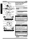
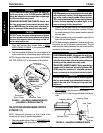
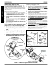
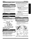
REPOSITIONING QUICK RELEASE
LEVERS (FIGURE 16)
NOTE: This procedure should only be performed if quick
release levers are on top of the axle mounting tube and
interfere with the desired rear seat-to-floor adjustment.
This procedure will position the quick release lever on
the bottom of the axle tube.
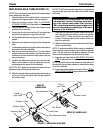
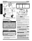
1. Remove the threaded knob from the quick release
lever.
2. Remove the quick release lever, recessed washer
and coved washer from the camber clamp.
3. If necessary, position the recessed washer and coved
washer onto the quick release lever, as shown in
FIGURE 16.
4. Insert the quick release lever with washers through
the camber clamp as shown in FIGURE 16.
5. Secure the quick release lever to the camber clamp
with the threaded knob.
6. Repeat for opposite quick release lever.
FIGURE 16 - REPOSITIONING QUICK RELEASE LEVERS
Threaded
Knob
Recessed
Washer and
Coved Washer
Quick Release Lever
Camber
Clamp
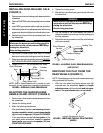
SIDE VIEW OF CAMBER CLAMP WITH QUICK
RELEASE LEVER
REVERSE POSITIONS
LEVER ON
CLAMP TOP
LEVER ON
CLAMP BOTTOM