


31
WHEELS PROCEDURE 5
WARNING
The locking pins MUST be protruding past
the inside of the rear wheel axle bushing
for a positive lock.
Keep locking pins clean.
5. If locking pins are not protruding past the inside of
axle bushing or there is too much movement of rear
wheel assembly in a back and forth position, refer to
ADJUSTING THE QUICK-RELEASE AXLE or RE-
MOVING THE PLAY FROM THE REAR WHEELS
in this procedure of the manual.
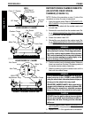
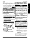
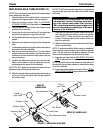
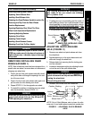
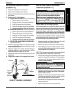
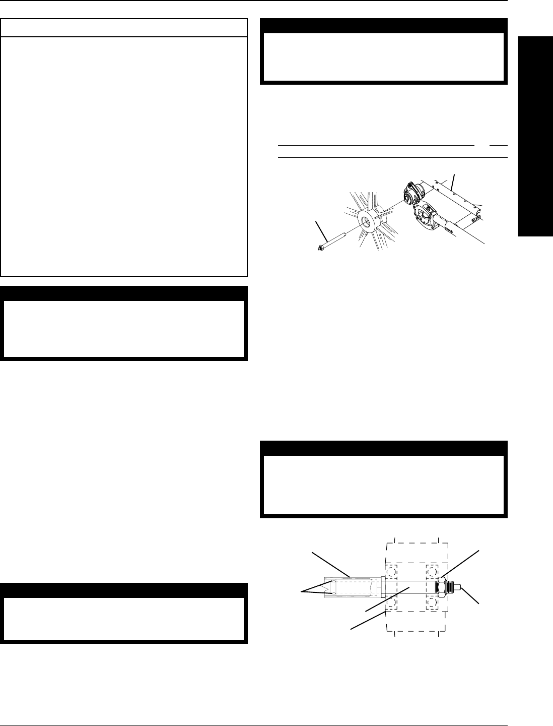
Quick-Release
Axle
Wheelchair
Frame
FIGURE 1 - REMOVING/INSTALLING REAR
WHEELS
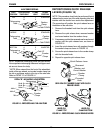
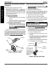
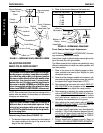
ADJUSTING QUICK-RELEASE
AXLE (FIGURE 2)
1. Remove rear wheel and quick-release axle from
the wheelchair.
2. Depress detent pin in the quick-release axle and
slide axle through the wheel hub.
3. Release detent pin ensuring that the locking pins
are fully released.
4. Increase or decrease end play by adjusting the lock-
nut on the end of the quick-release axle.
WARNING
Make sure the detent pin and locking pins of the
quick-release axle are fully released BEFORE op-
erating the wheelchair.
Keep locking pins clean.
5. Reinstall rear wheel onto the wheelchair.
W
H
E
E
L
S
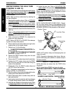
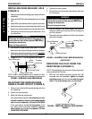
This Procedure includes the following:
Removing/Installing Rear Wheels
Adjusting Quick-Release Axle
Installing Quad-Release Axle
Adjusting the Quad-Release Handle In and/or Out
Removing the Play From the Rear Wheels
Handrim Replacement
Repairing/Replacing Rear Wheel Tire/Tube
Wheel Lock Adjustment/Replacement
Replacing/Adjusting Casters
Replacing Front Forks
Adjusting Caster Height
Installing Quick Release Casters
Adjusting Front Seat-To-Floor Height
WARNING
After ANY adjustments, repair or service and BE-
FORE use, make sure all attachment hardware is
tightened securely - otherwise, injury or damage
may result.
REMOVING/INSTALLING REAR
WHEELS (FIGURE 1)
NOTE: Each wheelchair frame has been designed for a
specific size rear wheel. Invacare does not recommend
changing rear wheel size.
1. Push in the tip of the quick-release axle (with wheel)
and pull the axle out through the opening in the cen-
ter of the rear wheel.
2. Push in the tip of the quick-release axle again and
pull the axle out of the existing rear wheel.
3. Repeat STEPS 1-2 for the opposite rear wheel.
4. To reinstall the existing or install the new rear wheel
onto the wheelchair, reverse STEPS 1-3.
WARNING
Make sure the detent pin and locking pins of the
quick/quad-release axle are fully released BE-
FORE operating the wheelchair.
Detent
Pin
Locknut
Locking
Pins
Camber Bushing
Wheel Hub
Quick- Release Axle
NOTE: End of Quick-Release axle is shown for refer-
ence only. It is not visible when inserted into camber bar.
FIGURE 2 - ADJUSTING QUICK-RELEASE
AXLE