


SECTION 5—BACK
Part No 1026793 35 Xtra™
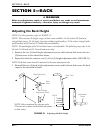
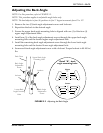
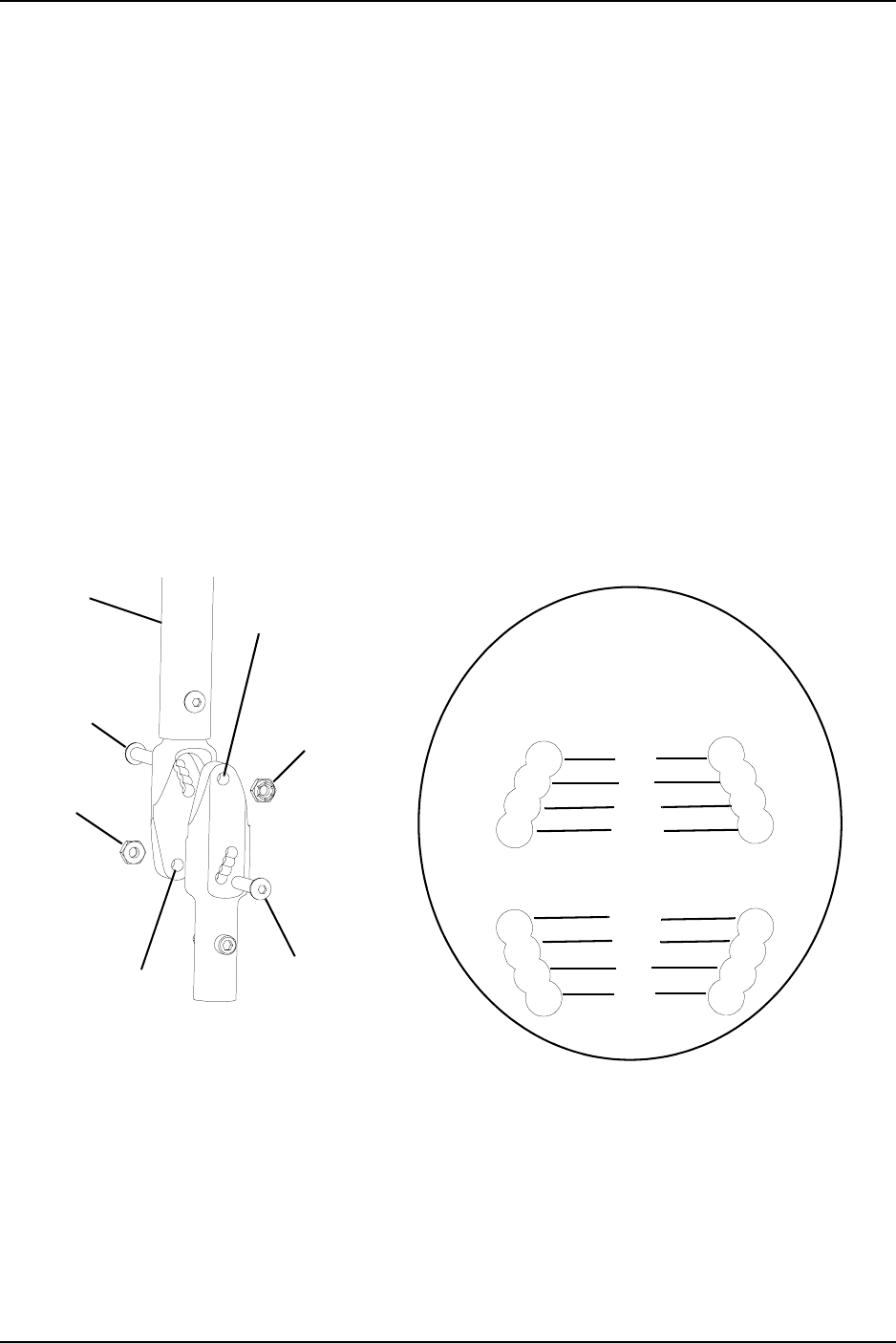
Adjusting the Back Angle
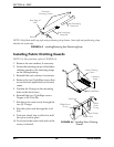
NOTE: For this procedure, refer to FIGURE 5.2.
NOTE: This procedure applies to adjustable angle backs only.
NOTE: The back adjusts to four (4) positions in five 5° degree increments from 0° to 15°.
1. Remove the two (2) back angle adjustment screws and locknuts.
2. Reposition the back to the desired angle.
3. Ensure the upper back angle mounting hole is aligned with one (1) of the four (4)
upper angle adjustment holes.
4. Install one (1) of the back angle adjustment screws through the upper back angle
mounting hole and the desired upper angle adjustment hole.
5. Install the remaining back angle adjustment screw through the lower back angle
mounting hole and the desired lower angle adjustment hole.
6. Secure each back angle adjustment screw with a locknut. Torque locknut to 80-100 in/
lbs.
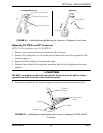
FIGURE 5.2 Adjusting the Back Angle
Back Cane
Locknut
Lower Back
Angle Mounting
Hole
Back Angle
Adjustment
Screw
Upper Back Angle
Mounting Hole
Detail "A" - back
angle mounting holes
Upper
0°
5°
10°
15°
Lower
0°
5°
10°
15°
Back Angle
Adjustment
Screw
Locknut