A-41
INSTRUCTION SET REFERENCE
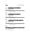
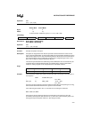
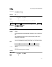
Operation: ANL
(CY) ← (CY) Λ (bit)
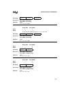
ANL CY,/bit
Binary Mode Source Mode
Bytes: 43
States: 3† 2†
†If this instruction addresses a port (P
x
,
x
= 0–3), add 1 state.
[Encoding]
Hex Code in: Binary Mode = [A5][Encoding]
Source Mode = [Encoding]
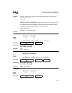
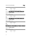
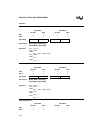
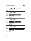
Operation: ANL
(CY) ← (CY) Λ Ø (bit)
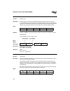
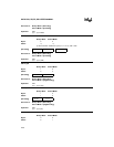
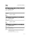
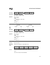
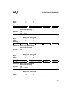
CJNE <dest>,<src>,rel
Function: Compare and jump if not equal.
Description: Compares the magnitudes of the first two operands and branches if their values are not
equal. The branch destination is computed by adding the signed relative displacement in the
last instruction byte to the PC, after incrementing the PC to the start of the next instruction. If
the unsigned integer value of <dest-byte> is less than the unsigned integer value of <src-
byte>, the CY flag is set. Neither operand is affected.
The first two operands allow four addressing mode combinations: the accumulator may be
compared with any directly addressed byte or immediate data, and any indirect RAM
location or working register can be compared with an immediate constant.
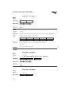
Flags:
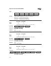
Example: The accumulator contains 34H and R7 contains 56H. After executing the first instruction in
the sequence
CJNE R7,#60H,NOT_EQ
; . . . . . . ;R7 = 60H
NOT_EQ: JC REQ_LOW ; IF R7 < 60H
; . . . . . . ;R7 > 60H
the CY flag is set and program execution continues at label NOT_EQ. By testing the CY flag,
this instruction determines whether R7 is greater or less than 60H.
If the data being presented to Port 1 is also 34H, then executing the instruction,
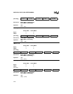
WAIT: CJNE A,P1,WAIT
clears the CY flag and continues with the next instruction in the sequence, since the
accumulator does equal the data read from P1. (If some other value was being input on P1,
the program loops at this point until the P1 data changes to 34H.)
1 0 1 0 1 0 0 1 1 1 1 1 0 y y y dir addr
CY AC OV N Z
✓ ——✓✓


