12-1
CHAPTER 12
SPECIAL OPERATING MODES
This chapter describes the power control (PCON) register and three special operating modes: idle,
powerdown, and on-circuit emulation (ONCE).
12.1 GENERAL
The idle and powerdown modes are power reduction modes for use in applications where power
consumption is a concern. User instructions activate these modes by setting bits in the PCON reg-
ister. Program execution halts, but resumes when the mode is exited by an interrupt. While in idle
or power-down, the V
CC
pin is the input for backup power.
ONCE is a test mode that electrically isolates the 8XC251Sx from the system in which it operates.
12.2 POWER CONTROL REGISTER
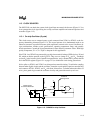
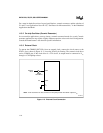
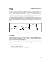
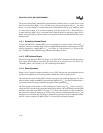
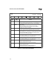
The PCON special function register (Figure 12-1) provides two control bits for the serial I/O
function, bits for selecting the idle and powerdown modes, the power off flag, and two general
purpose flags.
12.2.1 Serial I/O Control Bits
The SMOD1 bit in the PCON register is a factor in determining the serial I/O baud rate. See Fig-
ure 12-1 and section 10.6, “Baud Rates.”
The SMOD0 bit in the PCON register determines whether bit 7 of the SCON register provides
read/write access to the framing error (FE) bit (SMOD0 = 1) or to SM0, a serial I/O mode select
bit (SMOD0 = 0). See Figure 12-1 (PCON) and Figure 10-2 on page 10-3 (SCON).
12.2.2 Power Off Flag
Hardware sets the Power Off Flag (POF) in PCON when V
CC
rises from < 3 V to > 3 V to indicate
that on-chip volatile memory is indeterminate (e.g., at power-on). The POF can be set or cleared
by software. After a reset, check the status of this bit to determine whether a cold start reset or a
warm start reset occurred (see section 11.4, “Reset”). After a cold start, user software should clear
the POF. If POF = 1 is detected at other times, do a reset to reinitialize the chip, since for V
CC
<
3 V data may have been lost or some logic may have malfunctioned.


