8XC251SA, SB, SP, SQ USER’S MANUAL
A-26
A.4 INSTRUCTION DESCRIPTIONS
This section describes each instruction in the MCS 251 architecture. See the note on page A-11
regarding execution times.
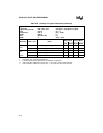
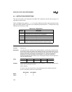
Table A-28 defines the symbols (
—, ✓, 1, 0,?) used to indicate the effect of the instruction on the
flags in the PSW and PSW1 registers. For a conditional jump instruction, “!” indicates that a flag
influences the decision to jump.
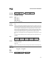
ACALL <addr11>
Function: Absolute call
Description: Unconditionally calls a subroutine at the specified address. The instruction increments the 3-
byte PC twice to obtain the address of the following instruction, then pushes bytes 0 and 1 of
the result onto the stack (byte 0 first) and increments the stack pointer twice. The destination
address is obtained by successively concatenating bits 15–11 of the incremented PC,
opcode bits 7–5, and the second byte of the instruction. The subroutine called must
therefore start within the same 2-Kbyte “page” of the program memory as the first byte of the
instruction following ACALL.
Example: The stack pointer (SP) contains 07H and the label "SUBRTN" is at program memory location
0345H. After executing the instruction
ACALL SUBRTN
at location 0123H, SP contains 09H; on-chip RAM locations 08H and 09H contain 25H
and 01H, respectively; and the PC contains 0345H.
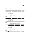
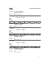
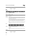
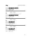
Binary Mode Source Mode
Bytes: 22
States: 99
Table A-28. Flag Symbols
Symbol Description
— The instruction does not modify the flag.
✓ The instruction sets or clears the flag, as appropriate.
1 The instruction sets the flag.
0 The instruction clears the flag.
? The instruction leaves the flag in an indeterminate state.
! For a conditional jump instruction: The state of the flag before the
instruction executes influences the decision to jump or not jump.
Flags: CY AC OV N Z
—————


