8XC251SA, SB, SP, SQ USER’S MANUAL
A-34
AJMP addr11
Function: Absolute jump
Description: Transfers program execution to the specified address, which is formed at run time by
concatenating the upper five bits of the PC (after incrementing the PC twice), opcode bits 7–
5, and the second byte of the instruction. The destination must therefore be within the same
2-Kbyte “page” of program memory as the first byte of the instruction following AJMP.
Flags:
Example: The label "JMPADR" is at program memory location 0123H. After executing the instruction
AJMP JMPADR
at location 0345H, the PC contains 0123H.
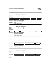
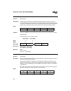
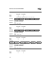
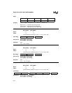
Binary Mode Source Mode
Bytes: 22
States: 33
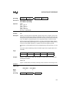
Hex Code in: Binary Mode = [Encoding]
Source Mode = [Encoding]
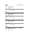
Operation: AJMP
(PC) ← (PC) + 2
(PC.10:0) ← page address
ANL <dest>,<src>
Function: Logical-AND
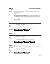
Description: Performs the bitwise logical-AND (Λ) operation between the specified variables and stores
the results in the destination variable.
The two operands allow 10 addressing mode combinations. When the destination is the
register or accumulator, the source can use register, direct, register-indirect, or immediate
addressing; when the destination is a direct address, the source can be the accumulator or
immediate data.
Note: When this instruction is used to modify an output port, the value used as the original
port data is read from the output data latch, not the input pins.
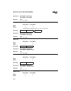
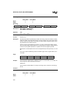
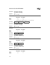
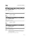
Flags:
CY AC OV N Z
—————
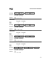
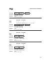
[Encoding] a10 a9 a8 0 0 0 0 1 a7 a6 a5 a4 a3 a2 a1 a0
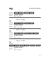
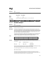
CY AC OV N Z
———✓✓


