


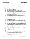

Airport Systems
PLC Health Monitoring & Reporting Sys 7-1 Manual EPM40002083-001 Rev -
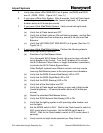
SECTION 7. APPENDIX A – EXAMPLES
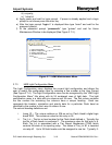
7.1 Light Configuration Examples
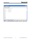
The HMS Light Configuration Menu provides the flexibility and configurability to address
most field installations. This section provides specific examples that demonstrate some
possible configuration values that are the results of choices made in the Light
Configuration Menu. The PLCHMR system has eight (8) relays that can report the
status of up to 24 Flash Heads. The Light Configuration menu enables the user to map
the status reporting from any combination of Flash Heads to any one or all 8 of the
relays. In section 3.4 it was declared that the relay’s state is controlled by the software
configured Tier Reporting Mechanism (TRM). Section 3.4 also indicated the TRM has
two states FLASH/OK and FAIL/FAULT. Software configuration of the TRM is
performed through the HMS Light Configuration Menu. Each TRM can be assigned
from zero to 24 Flash Heads. A Flash Head is assigned to a specific TRM via a
numeric entry in its corresponding Tier_Lvl column in the Light Configuration Menu. For
a TRM to activate its relay the status reported of all Flash Heads assigned to that tier
must be FLASH/OK. The TRM will deactivate its relay if any Flash Head assigned to it
reports a FAIL/FAULT status.
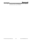
For instance consider the following example on how a system with 24 Flash Heads
could be configured:
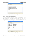
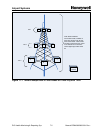
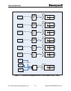
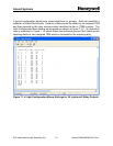
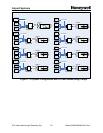
In the following example consider a system with nine Flash Heads arrange on 3 physical
tiers as shown in Figure 7.1-1.
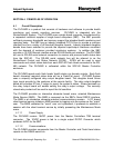
A typical configuration could use seven Tier Reporting Mechanisms TRMs. Each of the
top six Flash Heads could be assigned to its own individual TRM. The three lowest
Flash Heads would be assigned to one of the remaining TRMs. The Flash/Fail status
for the top six Flash Head would be collected by their assigned TRM and then reported
by a relay whose number identifies the tier or (TRM) number. This would result in the
top six Flash Heads having individualized status reports and the bottom three flash
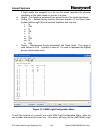
Heads having a collective status report. The Light Configuration Menu setting would
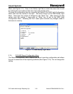
appear as shown in Figure 7.1-2. An alternative view is presented in Figure 7.1-3 which
shows the individual groups Flash Head groups reporting status to their assigned TRM
which is connected to the reporting relay.