


Airport Systems
PLC Health Monitoring & Reporting Sys 3-5 Manual EPM40002083-001 Rev -
3.3.3 PLCHMR Module Installation
The installation kit provides a PLCHMR module P/N 40002083 that is mounted inside
the Master Controller Enclosure. This module is mounted to four 2.5” high standoffs
and has five (5) wires to connect to the Master Controller board.
3.3.3.1 PLCHMR Module 2.5” Standoff Installation
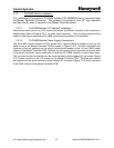
Remove and save the four (4) 6-32 screws that secure the Master Controller to the enclosure’s
bottom panel (Refer to
Figure 3.3-1 for exact screw locations). The four saved screws will be
used in a later step to secure the PLCHMR module mounting plate to the standoffs.
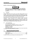
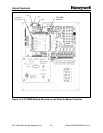
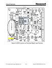
3.3.3.2 PLCHMR Module Power Supply Connections
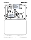
The PLCHMR module receives 16VDC power from Terminal Block-8 located on the top left
hand corner of the Master Controller PCB as shown in
Figure 3.3-2. Note the orientation and
locations of the two positions on the plug-in terminal with respect to the +16 and GND Labels
shown on the Master Controller PCB. Remove the two position plug-in terminal and loosen both
of the plug-in terminal’s screw sufficiently to install the PLCHMR module’s red and black wires.
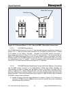
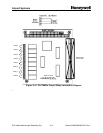
The red wire should be inserted into the screw terminal position labeled #2 as shown
Figure
3.3-3 which connects to the +16 contact on the Master Controller PCB. The black wire should
be inserted into the screw terminal position labeled #1 as shown
Figure 3.3-3 which connects
to the GND contact on the Master Controller PCB.