


Airport Systems
PLC Health Monitoring & Reporting Sys 3-7 Manual EPM40002083-001 Rev -
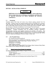
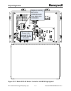
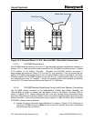
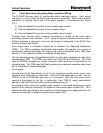
Red Wire
Black Wire
Figure 3.3-3 Terminal Block- 8 +16V - Red and GND –Black Wire Connections
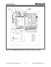
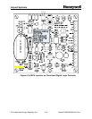
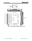
3.3.3.3 PLCHMR Module Mount
The PLCHMR module mounts to the four 2.5” high standoffs that were installed per directions in
Section 3.3.3.1. Note the location and orientation of the PLCHMR module as shown in
Figure
3.3-2 relative to the Master Controller. Oriented the PLCHMR module and place it
approximately as shown per
Figure 3.3-2 on the 2.5” high standoffs. Then re-connect the two
position PLCHMR power supply plug-in with its mating header block on the Master Controller.
Carefully position the PLCHMR module so that the four (4) mounting plate holes line-up with
four tapped bores in the 2.5” standoff. Secure the mounting plate to the standoff by installing
the four (4) 6-32 screws removed during the Section 3.3.3.1 activities.
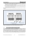
3.3.3.4 PLCHMR Module StrobeGuard Control and Status Network Connections
The PLCHMR module connects to the StrobeGuard Control and Status Network via
Terminal Block-5 which is located near the bottom center of the Master Controller PCB as
shown in
Figure 3.3-2. Before starting this task, note any existing wiring connections along
with their orientation and locations relative to the four position plug-in terminal connected to the
Master Controller. Remove the four position plug-in terminal. Install the White, Blue, and Black
PLCHMR’s network wires as directed:
a) Loosen the plug-in terminal’s screw labeled #1 as shown in
Figure 3.3-4 sufficiently to
insert the PLCHMR module’s White wire into terminal position along with maintaining
any existing wiring connections.