


Airport Systems
PLC Health Monitoring & Reporting Sys 3-8 Manual EPM40002083-001 Rev -
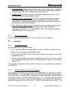
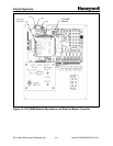
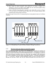
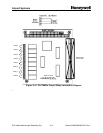
b) Next, loosen the plug-in terminal’s screw labeled #2 as shown in Figure 3.3-4
sufficiently to insert the PLCHMR module’s Blue wire into this terminal position along
with maintaining any existing wiring connections.
c) Finally, sufficiently loosen the plug-in terminal’s screw labeled #4 as shown in
Figure
3.3-4
and insert the PLCHMR module’s Black wire into the terminal position while
maintaining any existing wiring connections.
Reinstall the plug-in terminal onto its corresponding fixed mating header located on the Master
Controller.
Blue Wire
Black WireWhite Wire
1 2 3 4
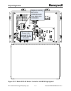
Figure 3.3-4 StrobeGuard Control & Status Network Wiring Connections
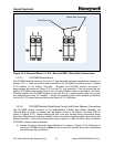
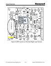
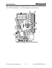
3.3.4 SGF-60-E Flash-head Digital Controller MCU Upgrade
The installation kit provides new MCUs P/N 40002084-001 to replace all existing old
MCUs P/N 40000324-001 in Flash Head Logic Control Board. See Figure 2.2-3 for the
location of Logic Control Board in the Flash Head Enclosure. It is important to install the
MCU with the proper orientation since more often than not installing a MCU backwards
will result in damage to the chip and/or surrounding circuitry. First note the location of
pin 1. To find pin 1 look for a small rectangular notch on one of its short ends this
denotes the top side of MCU; the first pin counter-clockwise from this notch is pin 1
.