


Installation
Topics Covered in this Chapter
♦ Location
♦ Install Air Solenoid
♦ Install Electronics Box and LCM
♦ Install Pressure Transducers
♦ Connect Air Hoses and Cables
Shutdown the XP Sprayer before installing your
pressure monitor kit. Follow the Shutdown and
Pressure Relief Procedure in the XP Sprayer
operation manual. All electrical wiring must be
done by a qualified electrician and comply with all
local codes and regulations.
The procedures in this section are specific to each
component of the pressure monitor kit. For sprayer
installation instructions, refer to the XP70 Sprayer
Operation manual.
Location
These pressure monitoring kits are not approved
for use in hazardous atmosphere locations.
Installing this kit on a XP Sprayer that is EX
approved, voids the approval. The EX mark should
be removed from the machine ID plate when this
kit is installed.
NOTICE
Do not store a XP Sprayer with a pressure monitor
kit outside in the rain. Use protective bag 16J717
to prevent damage to the electronic components,
used with the pressure monitor kit, when stored
outside.
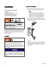
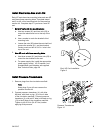
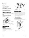
Install Air Solenoid
1. Disconnect the upper swivel and remove the
motor air line from the lower air manifold.
Note
On early XP sprayers, to remove the
existing air hose, it may be necessary to
remove the air filter assembly from the
XP and put it in a vice. New models XP
sprayers have an additional hose union.
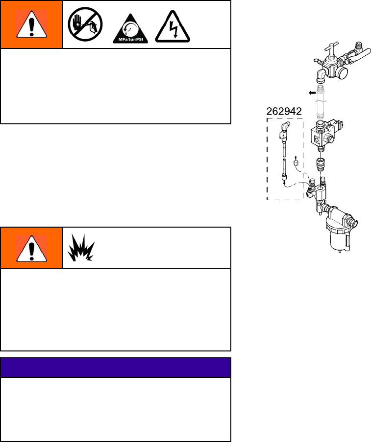
2. For the turbine powered kit 262942, remove a
plug from the air manifold and install the 5/16 in.
x 4 ft (1.2 m) air hose.
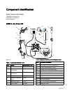
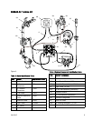
Figure 8
3. Connect the air solenoid valve and new motor
air hose to the air inlet assembly. Ensure that
the air solenoid valve cable faces the back of
the machine.
8 3A1331C