


1594A/1595A Super-Thermometer
RESISTANCE CALIBRATION (F4)
106
The reported data of the Ratio Self-Calibration may be written to a le on a USB memory device using the
WRITE FILE (F1) function key in the View Report screen (see Write File below).
The calibration parameters associated with measurement linearity may be adjusted to improve the accuracy if
necessary using the ADJUST PARAMETERS (F2) function key (see Adjust Parameters below).
The following function keys are found in the View Report screen.
9.4.1 WRITE FILE (F1)
The Write File function allows the user to write the Ratio Self-Calibration report to a le on the USB memory
device.
The user may change the le name by pressing the ENTER key to open the Alpha-Numeric interface and
entering a le name. Once the le name is set, and after the USB memory device is inserted into the front
USB port, the user presses the CONTINUE (F1) function key to proceed to write the le. The le is stored in a
folder named “\159x\test”. If the le already exists, the new test results are added to the le.
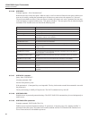
The results of each individual test in a Ratio Self-Calibration are written to the le as follows:
LINEARITY,<test>,<tolerance>,<error>,<% of tol>,<SE>,<date and time>
<test> is the test number, 1 through 8
<tolerance> is the specied tolerance in units of 1×10
-6
<error> is the error in units of 1×10
-6
<% of tol> is the absolute value of the error divided by the tolerance, expressed in percent
<SE> is the standard error of the test result error in units of 1×10
-6
<date and time> is the date and time of the test. The date is in the format YYYY-MM-DD. The time is in 24-
hour format.
9.4.2 ADJUST PARAMETERS (F2)
The Adjust Parameters function allows the user to update the linearity parameters (LINEARITY C1, LINEAR-
ITY C2, LINEARITY C3, and LINEARITY C4) to correct error observed during the Ratio Self-Calibration.
The Adjust Parameters function is always password protected. The user will be prompted to enter the correct
password to continue.
The screen shows the previous values of the calibration parameters and proposed new values based on calcula-
tions using the Ratio Calibration test results. The user presses YES (F4) to change the values of the linearity
parameters in memory. The user may press the NO (F5) function key or the EXIT key to cancel the change.
When completed, the linearity calibration parameters will be automatically adjusted to correct for the er-
rors observed during the Ratio Self-Calibration. The linearity parameters may be viewed in the Calibration
Parameters screen (see Calibration Parameters section). Ratio Self-Calibration should be repeated to verify the
calibration.
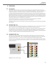
9.5 RESISTANCE CALIBRATION (F4)
The Resistance Calibration function allows the user to test and calibrate each of the internal reference resis-
tors. It requires a calibrated standard resistor of approximately the same resistance as the internal resistor that
will be calibrated.
No password is required to run Resistance Calibration since it rst measures an internal resistor without mak-
ing any adjustment to its internal calibration parameter. After an internal resistor is measured, the results are
displayed allowing the user to observe the results and decide if an adjustment is necessary.
Resistance Calibration works by measuring an internal resistor against a calibrated standard resistor. The inter-
nal resistor’s calibration parameter is adjusted to correct for error.