Caution!
The content of the totalizer is deleted in the event of power failure or disconnection of the
power supply!
Skipping to the submenu BARGRAPH or PIPE SIZE is effected depending on the selected menu
option.
5.7 Bar graph (menu option: BARGRAPH)
This menu option allows the user to set the bar graph as desired. The following settings should
be made:
• FLOW / TEMP = (bar graph assignment: flow rate/medium temperature)
• ZERO = (initial value of the bar graph)
• FS = (final value of the bar graph)
Independent of its assignment, the bar graph has a constant resolution of 10 segments.
When entering the initial or final value, the user should observe reasonable resolution!
The bar graph also comprises the representation of the limit switch(es) as far as they can be
indicated in the bar range selected.
The representation of the limit switches in the bar graph depends on the switch-on value of the
limit switch.
For representation details see para. 4.2.1 (Operating data).
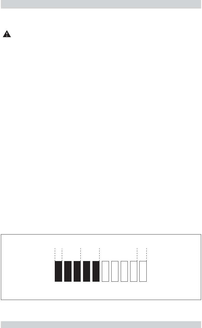
Example:
Limit switch assignment: LS1 F and LS2 T
Switch-on value LS2: 23 °C
Switch-off value LS2: 29 °C
Analogue bar graph assignment: medium temperature
Initial value - analogue bar graph: 20 °C
Final value - analogue bar graph: 30 °C
Instantaneuous temperature value: 25 °C
resulting in the analogue bar graph display shown below:
Flow Meter FC01-LQ Flow Meter FC01-LQ
Configuration 33 Configuration 33
20 °C 21 °C 25 °C 29 °C 30 °C
LS2 ON
T T
23 °C
fig. 22
20 °C 21 °C 25 °C 29 °C 30 °C
LS2 ON
T T
23 °C
fig. 22


