


Flow Meter FC01-LQ Flow Meter FC01-LQ
Installation 17 Installation 17
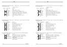
2.3.2 Electrical connection
Valid for all plug-in screw terminal strips:
Cable size: 0.14 mm
2
to 1.5 mm
2
, single or stranded conductor
Stripping length: 6.5 mm
Clamping screw: M2 (nickel-plated brass)
Contact material: pre-tinned tin bronze
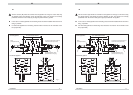
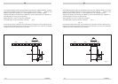
XV - Power supply
Connection by 3 pole connector; max. 1.5 mm
2
; 3 x 0.75 mm
2
cable recommended
Pin No. Signal name Function
1 SGND general reference ground/shield ground
2+U
V
positive pole of supply voltage
3-U
V
negative pole of supply voltage
XTF - Keyboard release
Connection by 3 pole connector; factory-wired
Bridge 2-3 inserted = keyboard blocked
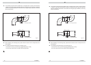
2.3.2 Electrical connection
Valid for all plug-in screw terminal strips:
Cable size: 0.14 mm
2
to 1.5 mm
2
, single or stranded conductor
Stripping length: 6.5 mm
Clamping screw: M2 (nickel-plated brass)
Contact material: pre-tinned tin bronze
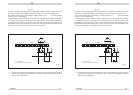
XV - Power supply
Connection by 3 pole connector; max. 1.5 mm
2
; 3 x 0.75 mm
2
cable recommended
Pin No. Signal name Function
1 SGND general reference ground/shield ground
2+U
V
positive pole of supply voltage
3-U
V
negative pole of supply voltage
XTF - Keyboard release
Connection by 3 pole connector; factory-wired
Bridge 2-3 inserted = keyboard blocked
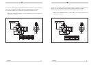
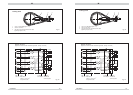
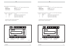
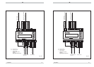
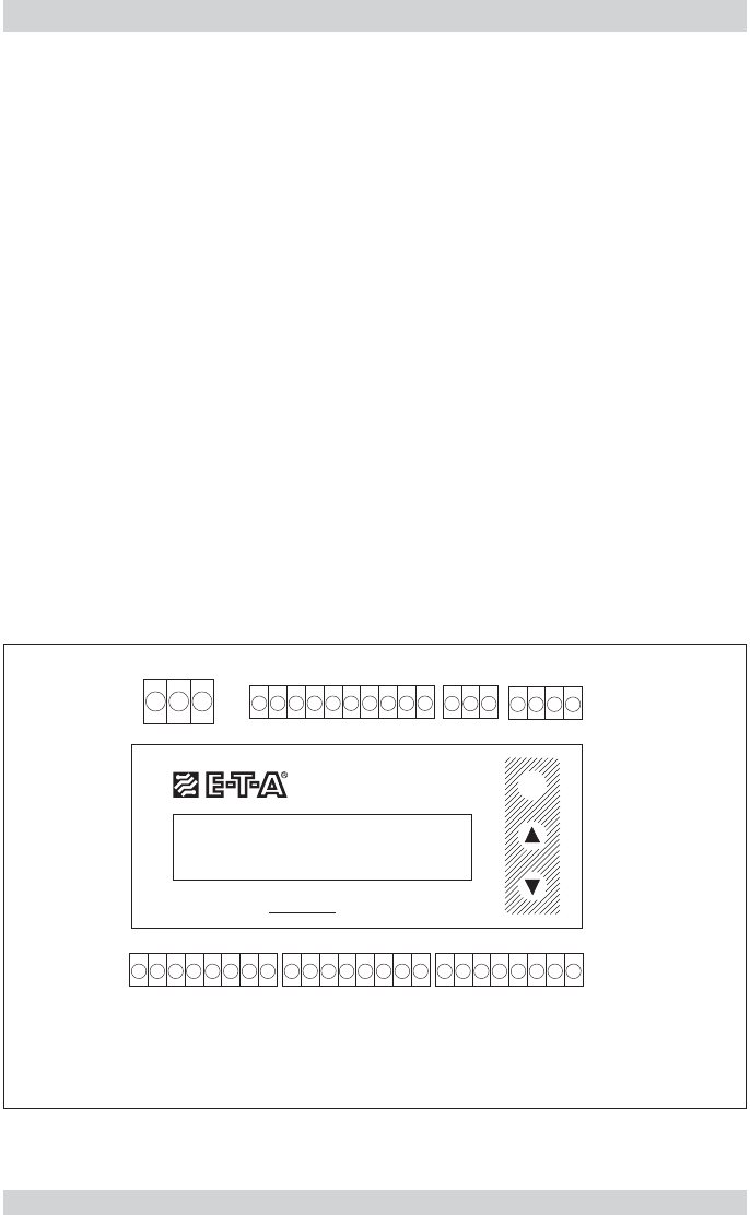
X
V - power supply
X
SK - calorimetric monitoring head
X
TF - keyboard release
(XAS) - nor released for user
XAO - analogue outputs
XAH - signal outputs
123
1234
XV XSK XTF
(XAS) XAO XAH
1
2345678910
123
8
7654321
8
7654321
8
7654321
M
FC01-LQ
Flow Controller
fig. 14
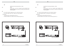
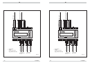
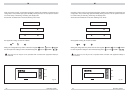
X
V - power supply
X
SK - calorimetric monitoring head
X
TF - keyboard release
(XAS) - nor released for user
XAO - analogue outputs
XAH - signal outputs
123
1234
XV XSK XTF
(XAS) XAO XAH
1
2345678910
123
8
7654321
8
7654321
8
7654321
M
FC01-LQ
Flow Controller
fig. 14