


Flow Meter FC01-LQ Flow Meter FC01-LQ
28 Operation and main menu 28 Operation and main menu
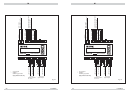
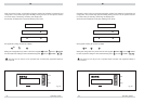
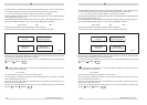
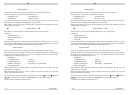
The limit switches are identified according to their physical assignment, i.e. by F for flow rate and
T for medium temperature, at the first or last place of the second line on the display.
If F and T are shown reversed, the limit switch is in the switch-on condition.
Limit switches lying within the analogue bar range are also represented at the appropriate place
of the analogue bar (see para. 5.7).
The following figures show the display variants under menu option “Measured value(s)” (para. 5.6 -
menu option DISPLAY SELECT and 5.9 - menu option FREQUENCY OUTPUT).
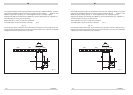
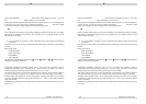
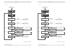
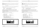
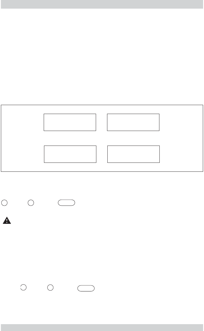
4.2.1.2 Peak values (menu option: PEAK VALUE MIN / PEAK VALUE MAX)
The FC01-LQ comprises four specific measured-values memories.
They store the lowest and highest value of flow rate and medium temperature.
MIN VALUE
flow rate
MAX VALUE
flow rate
MIN VALUE
medium temperature
MAX VALUE
medium temperature
fig. 21
After switch-on or NOT-BUSY indication, the minimum and maximum values are deleted and will
be continuously updated (non-return pointer principle).
The peak values may be retrived in the main menu and are deleted by simultaneously pressing
UP and DOWN = .
Caution!
Power failure or disconnection of the power supply will delete the contents of the four
measured-values memories.
4.2.1.3 Last error (menu option: LAST ERROR)
The last main menu option to be called is the error memory.
This error memory comprises the number of the last error (see section 7). It may be very helpful
when commissioning the FC01-LQ.
Other than the peak value memories described above, the contents of this memory will be
retained even upon power failure.
The user may purposely delete the error memory in the condition selected by simultaneously
pressing UP and DOWN = .
▲
▼
▲
+
▼
▲
▼
▲
+
▼
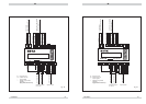
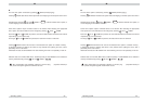
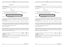
The limit switches are identified according to their physical assignment, i.e. by F for flow rate and
T for medium temperature, at the first or last place of the second line on the display.
If F and T are shown reversed, the limit switch is in the switch-on condition.
Limit switches lying within the analogue bar range are also represented at the appropriate place
of the analogue bar (see para. 5.7).
The following figures show the display variants under menu option “Measured value(s)” (para. 5.6 -
menu option DISPLAY SELECT and 5.9 - menu option FREQUENCY OUTPUT).
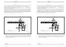
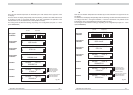
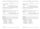
4.2.1.2 Peak values (menu option: PEAK VALUE MIN / PEAK VALUE MAX)
The FC01-LQ comprises four specific measured-values memories.
They store the lowest and highest value of flow rate and medium temperature.
MIN VALUE
flow rate
MAX VALUE
flow rate
MIN VALUE
medium temperature
MAX VALUE
medium temperature
fig. 21
After switch-on or NOT-BUSY indication, the minimum and maximum values are deleted and will
be continuously updated (non-return pointer principle).
The peak values may be retrived in the main menu and are deleted by simultaneously pressing
UP and DOWN = .
Caution!
Power failure or disconnection of the power supply will delete the contents of the four
measured-values memories.
4.2.1.3 Last error (menu option: LAST ERROR)
The last main menu option to be called is the error memory.
This error memory comprises the number of the last error (see section 7). It may be very helpful
when commissioning the FC01-LQ.
Other than the peak value memories described above, the contents of this memory will be
retained even upon power failure.
The user may purposely delete the error memory in the condition selected by simultaneously
pressing UP and DOWN = .
▲
▼
▲
+
▼
▲
+
▼
▼
▲