


Section 1
General Information
A-2 Appendix A MN770
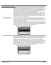
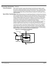
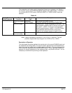
The parameters and inputs used for torque feed forward are indicated in the Table A-1.
For a Vector control, the OPERATING MODE selected will be BIPOLAR or 15 SPEED.
For a Series 20H DC SCR control, BIPOLAR HOIST or 7 SPEED HOIST should be
selected.
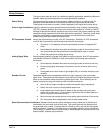
Table A-1
Analog Command
Select Parameter
Input Terminal
Location
Input Range and
Type
Description
10V W/TORQ FF J1-4, 5
(J4-4, 5 for Inverter)
–10 to +10VDC
Differential
This input is bipolar. The polarity of the signal selects
the direction and speed of travel.
J1-2
(J4-2 for inverter)
–10 to +10VDC This input is bipolar and controls the Torque Feed
Forward value. Torque is proportional to current. The
input voltage is scaled to the PK Current Limit value of
the control. +10VDC = PK Current Limit parameter
value for positive torque, +5VDC= 1/2 the PK Current
Limit parameter value and 0VDC= zero current.
Negative input voltages represent negative torque.
J1-1
(J4-1 for inverter)
common Input reference (J1-2 or J4-2).
Note: It may be necessary to connect J1-4 or J1-5 to J1-1 (ground). This will
provide a single ended input range of 0 to 10VDC or 0 to –10VDC.
Description of Operation
This input signal should be applied to the control prior to the control ENABLE signal and
the release of the holding brake. The control will then generate the commanded torque
when the control is enabled and the holding brake is released. This occurs because the
initial current will be greater than the MAG AMPS value. This will generate torque and
because it is directly proportional to the measured load, it will prevent roll back. It is not
necessary to remove this input during normal operation.