


Section 5
Set-Up Information
Set-Up Information 5-1MN770
DC SCR Controls DC motors use voltage to obtain their speed and current to develop their output torque.
A DC SCR control must be able to supply the required voltage and current to operate the
motor under all conditions of load and speed.
Note: Do not assume that having the required horsepower is sufficient information to
size the control. You will need to know the maximum voltage and current. The
motor nameplate should be the source for the RMS (continuous) ratings but
actual measurements should be made to determine the maximum required
current and voltage with the elevator loaded to capacity.
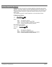
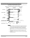
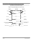
Field Control Remember that the Series 20H control’s DC output is a maximum of 113% of input
voltage for the armature and up to 85% of input voltage for the field. This means that if
the field voltage is more than 195 volts for a 230 volt AC line, a single phase transformer
must be used to boost the AC input to the field power module. Some gearless elevator
DC motors have odd voltages which need to be supplied from special controls through
isolation transformers.
All Series 20H field power modules can be operated from 480 VAC or less, regardless of
the catalog or spec number of the control. The standard field power supply module is
rated for 15 amps maximum, but a 40 amp field power module is available as an option.
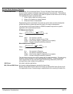
Feedback Most elevator DC controls operate closed loop which means that the motor speed is fed
back to the control using a DC tachometer, encoder or resolver. The feedback device is
usually coupled to the motor shaft but also may operate from a wheel on the sheave. A
DC tachometer is the most common feedback device and this requires the EXB006A01
expansion board mounted in the Series 20H.
Gearless elevators often benefit from using encoder feedback due to the higher
resolution of the feedback signal during low speed (leveling) conditions. The Encoder
interface is built into in the Series 20H while a DC tach or resolver feedback requires an
expansion board. A DC tach may be used on a gearless elevator but it should be
optimized to give a high DC volts per RPM output.
Typical DC tachometers provide 50, 60, 100 or 200 volts DC output per 1000 RPM when
coupled 1:1 to the motor. Encoders are usually 1000 or 1024 pulses per revolution (PPR).
Note: The boosted voltage must be in phase with the incoming lines L1 and L2.
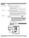
Initial Installation and Startup When installed in a panel, the Series 20H control should be located away from
sources of heat and in an area where the keypad is visible and convenient to operate.
See the Series 20H manual (MN720) for additional installation information, watts loss
requirements, and other information regarding the selection of a mounting location. Any
required expansion boards should be installed before applying power.
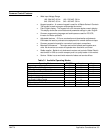
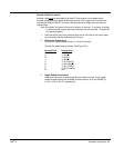
Preliminary programming should include setting the following:
1. Level 1 Input Block, Operating Mode.
2. Level 1 Output Block, Opto Output values.
3. Level 1 DC Control Block, all parameters.
4. Level 2 Output Limits Block, all parameters.
5. Level 2 Motor Data Block, all parameters.
Other parameters will be set after final installation.
Note: In many elevator applications the BIPOLAR HOIST MODE is used with the
elevator controller as well as an external S-Curve generator.