


Section 1
General Information
5-12 Set-Up Information MN770
Initial Set-up Continued
j. Set Level 1 VECTOR CONTROL Block, SLIP FREQUENCY as desired.
This value can be calculated from the values recorded previously in Table
5-2. Record these calculated values in Table 5-3.
Calculate the Slip RPM of the motor:
Slip RPM + (RPM of Balanced Car) * (RPM of Fully Loaded Car)
Calculate the % of Motor Loading:
% Rated Motor Load +
ǒ
Full Load AC Motor Current
Rated Motor Amps
Ǔ
X 100%
Determine the Slip Adjustment Value from Table 5-1.
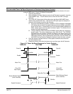
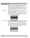
Table 5-1 Slip Adjustment Value.
% Rated Motor Load Slip Adjustment Value
100 - 110% 1.0
90 - 100% 1.1
80 - 90% 1.3
70 - 80% 1.5
Calculate the Slip Frequency parameter value:
Slip Frequency +
Line Frequency x Slip RPM x Slip Adjustment Value
RPM of Balanced Car
k. Set Level 2 Operating Zone as desired (usually Quiet Constant Torque).
l. Set Level 2 Output Limits block, MIN OUTPUT SPEED parameter.
m. Set Level 2 Output Limits block, MAX OUTPUT SPEED parameter.
n. Set Level 2 MOT
OR DA
TA block parameters:
Motor Voltage (input)
Motor Rated Amps (FLA)
Motor Rated Speed (Base Speed)
Motor Rated Frequency
Motor Mag Amps (no load current)
4. Manual Tuning Method - Because the load cannot be uncoupled from the motor
shaft, proceed with the manual tuning procedure. The manual tuning procedure
is provided in MN718 for the Series 18H Vector Control.
Final Set-up After Initial Set-up is complete, operate the elevator using the Vector control and make
any final adjustments. Accel, Decel and S-Curve values may need adjustment for
smooth operation.