


Section 1
General Information
Troublehsooting 6-7MN770
Wiring Practices
The type of wire used and how it is installed for specific applications makes the difference
between obtaining reliable operation and creating additional problems.
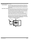
Power Wiring Conductors carrying power to anything (motor, heater, brake coil, or lighting units, for
example) should be contained in conductive conduit that is grounded at both ends.
These power wires must be routed in conduit separately from signal and control wiring.
Control–logic Conductors Typically, operator’s controls (push buttons and switches), relay contacts, limit switches,
PLC I/O’s, operator displays, and relay and contactor coils operate at 115VAC or 24VDC.
Although these devices usually operate at low current levels, they contain switching noise
caused by contact open/closure and solid–state switch operations. Therefore, these wires
should be routed away from sensitive signal wires and contained within conduits or
bundled away from open power and signal wires.
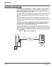
DC Tachometer Circuits Among the most sensitive circuits is the DC Tachometer. Reliability of a DC tachometer
circuit is often improved by the following noise reduction techniques:
• Connect a 0.1 mf capacitor across the tachometer terminals to suppress AC
noise.
• Use twisted-pair shielded wires with the shield grounded at the control end only.
You should avoid grounding the shield to the tachometer case or conduit.
• Follow the practices for analog signal wiring.
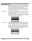
Analog Signal Wires Analog signals generally originate from speed and torque controls, plus DC tachometers
and process controllers. Reliability is often improved by the following noise reduction
techniques:
• Use twisted-pair shielded wires with the shield grounded at the drive end only.
• Route analog signal wires away from power or control wires (all other wiring
types).
• Cross power and control wires at right angles (90°) to minimize inductive noise
coupling.
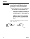
Encoder Circuits Adjustable speed drives are especially sensitive to high frequency noise on encoder
signal lines. Because these input signals cannot be heavily filtered special care must be
taken to avoid transient noise from entering these signal lines. Drive reliability can be
greatly improved by using the following noise reduction techniques:
• Use line driver output encoders to reduce the encoder output impedance.
• Select line driver inputs on the adjustable speed drive.
• Install twisted-pair shielded wire for power to the encoder and having each
output with its own return. (Avoid common conductors with multiple outputs or
with an output and the power source.)
• Never connect the encoder ground to the power ground terminal of the control.
• Run all encoder wires independently from all other power wires.
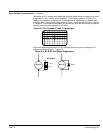
Serial Communication Conductors Standard serial communication cables are usually made with a shield that is
connected to the connector shell at both ends. This usually grounds the data source to
the grounded drive chassis. If the data source is floating, such a connection offers good
data transmission. However, if the data source is grounded, adding a heavy ground wire
(#14 or larger) in parallel with the communication cable between the source and the drive
chassis usually reduces noise problems.