


Section 1
General Information
6-2 Troublehsooting MN770
Electrical Noise Considerations All electronic devices including a Series H Control are vulnerable to significant
electronic interference signals (commonly called “Electrical Noise”). At the lowest level,
noise can cause intermittent operating errors or faults. From a circuit standpoint, 5 or 10
millivolts of noise may cause detrimental operation. For example, analog speed and
torque inputs are often scaled at 5 to 10 VDC maximum with a typical resolution of one
part in 1,000. Thus noise of only 5 mv represents a substantial error.
At the extreme level, significant noise can cause damage to the drive. Therefore, it is
advisable to prevent noise generation and to follow wiring practices that prevent noise
generated by other devices from reaching sensitive circuits. In a control, such circuits
include inputs for speed, torque, control logic, and speed and position feedback, plus
outputs to some indicators and computers.
Causes and Cures Unwanted electrical noise can be produced by many sources. Depending upon the
source, various methods can be used to reduce the effects of this noise and to reduce the
coupling to sensitive circuits. All methods are less costly when designed into a system
initially than if added after installation.
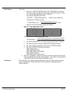
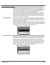
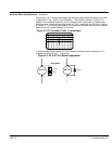
Figure 6-1 shows an oscilloscope trace of noise induced (as the coil circuit is opened) in
a 1–ft. wire located next to a lead for a Size 2 contactor coil. Scope input impedance is
10KW for all scope traces. Maximum peak voltage is over 40V. Unless well filtered this is
often enough noise to ruin the output of a productive machine.
Figure 6-1 Electrical Noise Display
Relay and Contactor CoilsAmong the most common sources of noise are the ever–present coils of contactors and
relays. When these highly inductive coil circuits are opened, transient conditions often
generate spikes of several hundred volts in the control circuit. These spikes can induce
several volts of noise in an adjacent wire that runs parallel to a control–circuit wire.
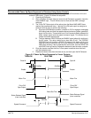
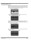
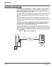
To suppress noise in these AC coils, add an R–C snubber across each relay and
contactor coil. A snubber consisting of a 33KW resistor in series with a 0.47
mf capacitor
usually works well. The snubber reduces the rate of rise and peak voltage in the coil
when current flow is interrupted. This eliminates arcing and reduces the noise voltage
induced in adjacent wires. In our example, the noise was reduced from over 40 V
zero–to–peak (V0P) to about 16 V0P as shown in Figure 6-2.
Figure 6-2 R-C Snubber Circuit