


Section 1
General Information
Set-Up Information 5-13MN770
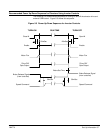
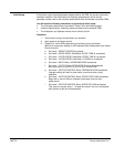
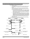
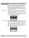
Recommended Power Up/Down Sequence for Elevators Using Vector Controls
The following is a recommended sequence for turning on and off the elevator drive and
external OEM control. Figure 5-2 shows this sequence.
1. Close the M-Contactor.
2. After a 20mSec minimum delay (to ensure the M Contactor is closed), close the
drive ENABLE input. This will allow current to flow and the IGBT’s to begin
switching.
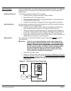
3. The “Drive ON” Opto output will be active when the Motor MAG AMPS have
reached the programmed value. Use the Drive ON opto output to energize an
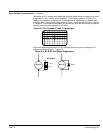
external coil for a relay to perform the following:
A.
Signal
the OEM elevator controller
,
computer or PLC to engage or disengage
the
holding brake and feed the speed command reference (pattern
generator)
signal into the drive. There should be a 50 milli-seconds delay between the
brake release signal and the speed command signal. This allows time to
release the brake mechanically.
B.
The
time between DRIVE
ON and the ENABLE signal allows flux build-up in
the AC motor. This delay should be no less than 20 mS. The TORQUE
PROVING fault will prevent a DRIVE ON output if the Vector drive is not
applying
current to the motor due to an open contactor
, broken motor lead or
open
motor
winding. If during operations a fault occurs, then the DRIVE ON
and
READY
both go inactive, engage the brake and open the motor contactor
.
4. Once the elevator reaches the floor, a zero speed command should be held
until the brakes are set.
5. Disable the Vector drive after the brake is set, and then open the M-Contactor.
Figure 5-2 Power Up/Down Sequence for Vector Controls.
Close M Open M
Enable
20mSec
Enable
20mSec
Motor Flux
“Drive ON”
Opto Output
Brake Release Signal
(from controller)
Motor Flux
“Drive ON”
Opto Output
Brake Release Signal
(from controller)
50mSec
Speed Command
50mSec
Speed Command
RUN TIMETURN-ON TURN-OFF
Brake Set Time