


Section 1
General Information
5-8 Set-Up Information MN770
Vector Controls If this is a modernization, do not disconnect the old control from the motor. It is needed to
operate the motor for some preliminary measurements before it is disconnected. See
Modernization.
Equipment Required The following equipment is required for this upgrade.
1. Elevator rated AC induction motor with encoder installed.
2. Baldor Series 18H or 22H Vector Control.
3. Elevator system controller (PLC-not supplied by Baldor). This controller will be
connected to the Vector Control.
4. Clamp-On AC Amp Meter. (Voltage and Current range depend on the motor).
New Installations For new elevator installations that are pre-configured by the OEM, perform the following:
(Skip this procedure if this is a modernization).
1. Install the motor and Vector Control. Refer to the Installation and Operating
Manual supplied with the control for mounting and wiring instructions.
2. Refer to the Installation and Operating manual. Perform the following parts of
the Manual Tuning procedure: CALC Presets, CMD Offset Trim and CUR Loop
Comp. Be sure the motor contactor is closed for the CUR Loop Comp test.
3. Apply power. Adjust the Level 1 Vector Control block, Current Prop Gain and
Speed Prop Gain parameter values for best ride.
Modernization For modernization of an existing installation, perform these steps instead
of those for
“New Installation”:
Caution: Check the motor nameplate ratings and the input voltage at the
power source and be sure that they match. If the measured input
voltage is different than the rated voltage on the nameplate do not
proceed. The Vector control ratings must match the motor ratings
and the input line voltage. If the Vector Control nameplate shows
the input voltage and frequency required for proper operation.
Other input power may damage the control. Refer to the Vector
Control manual for installation considerations.
1. Disconnect all elevator power.
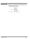
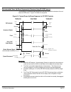
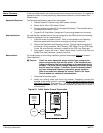
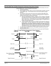
2. Modify the existing motor and mount the encoder. Temporarily connect the
encoder to the Vector control J1 terminals
(Do not connect the motor leads to
the Vector Control)
. See Figure 5-1. The existing elevator control will be used
to drive the load for these tests. Encoder connections are describe in Section 4
of this manual.
Figure 5-1 Initial Vector Control Connection
Existing
Elevator
Control
Wiring
Motor
Encoder
LOCAL
SHIFT
DISP
RESET
PROG
ENTER
JOG
STOP
REV
FWD
Temporary
Connection