


33
Appendix
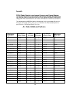
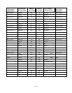
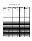
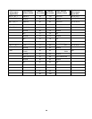
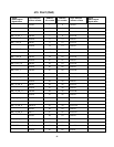
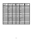
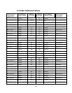
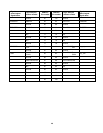
FS2343 Paddle Signal to Logic Analyzer Connector and Channel Mapping
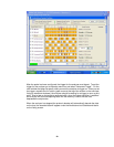
The following table shows how the FS2343 Probe connects FBDIMM AMB signals to the
logic analyzer pods and channels through the 100 pin Samtec connectors. Note that the
configuration files described earlier use various combinations of these Pod connections.
The nomenclature is NB/SB for North or Southbound, Lx for Lane number, Bx for bit in
during the rising edge of Anly_clkp, and _xx is the bit for the Dual sampled (second)
point which is on the falling edge of Anly_clkp.
J9 - Pods 1(Odd) and 2 (Even)
Signal
name/Logical
Signal Name
Logic Analyzer
channel number
SAMTEC
Pin number
SAMTEC
Pin number
Logic Analyzer
channel number
Signal
Name/Logical
Signal name
Ground 1 2 Ground
NC 3 4 NC
Ground 5 6 Ground
NB_L1_B0_6 Odd D0 7 8 Even D0 MODE
Ground 9 10 Ground
NB_L1_B4_10 Odd D1 11 12 Even D1 NB_L1_B2_8
Ground 13 14 Ground
NB_L0_B5_11 Odd D2 15 16 Even D2 FRAME
Ground 17 18 Ground
NB_L0_B3_9 Odd D3 19 20 Even D3 NB_L0_B4_10
Ground 21 22 Ground
NB_L1_B1_7 Odd D4 23 24 Even D4 NB_L2_B1_7
Ground 25 26 Ground
NB_L1_B5_11 Odd D5 27 28 Even D5 NB_L2_B0_6
Ground 29 30 Ground
NB_L0_B2_8 Odd D6 31 32 Even D6 NB_L1_B3_9
Ground 33 34 Ground
NB_L0_B1_7 Odd D7 35 36 Even D7 NB_L3_B2_8
Ground 37 38 Ground
NB_L2_B4_10 Odd D8 39 40 Even D8 NB_L3_B0_6
Ground 41 42 Ground