


22
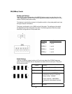
Event Bus Cabling
The Event Bus bits, Evbus[0:3], from other probes can be daisy chained across multiple
probes in order to provide cross probe control of other probes. There are 2 EV cable
connectors on each probe and both connectors are wired in parallel so that either can
be used. Additionally, the probe has termination sensing circuitry so that the Evbus[0:3]
signals are properly terminated on the probe if the cables are not used.
The cables are connected at either J9 or J10 on the board with their wires exiting the
board from the top. LED D1 will light if the cables are attached backwards.
Probe Control Application
The FS2343 Interposer probe is controlled from a Probe Add-in, which has to be
installed on the 16900 workspace as it communicates through the logic analyzer cards
through an internal SM (SMBus) port which is connected to the probe by means of the
adapter cable connection.
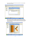
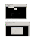
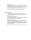
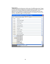
Loading the Probe Control Software
Load the CD provided with the probe into the 16900 frame and locate the file FBD Probe
Control.exe. Double-click this file and it will install and be available in the Agilent Logic
analyzer software under the Setup tab as the FBDIMM Probe.
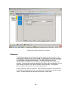
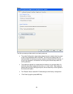
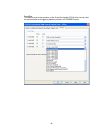
Using the Probe Control Software
Always use the “Apply” button before changing windows or using the “OK” button. It is
important to note that the probe control software sets up registers within the AMB. It is
still necessary to set up parameters in the configuration file for triggers, storing, filtering
etc. Setting up the AMB through the probe control software generates signals going to
the logic analyzer, the logic analyzer can then use these signals to qualify, trigger or
filter events or data of interest.
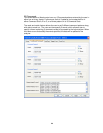
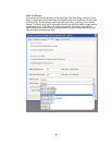
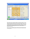
Please see the following pages for details for the different register settings within the
AMB.