3-9CrossPoint 450 Plus and MAV Plus Switchers • Operation
Power indicators (2412 and larger models only)
9
Primary and Redundant Power Supply LEDs —
Green — Indicates that the associated power supply is operating within
normal tolerances.
Red — Indicates that the associated power supply is operating outside the
normal tolerances or has failed.
Button icons
The numbered translucent covers on the input and output pushbuttons can be
removed and replaced to insert labels behind the covers.
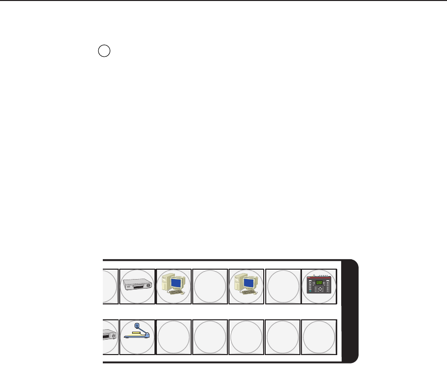
Input and output labels can be created easily with Extron’s Button-Label Generator
software, which ships with every Extron matrix switcher. Each input and output
can be labeled with names, alphanumeric characters, or even color bitmaps for easy
and intuitive input and output selection (figure 3-4). See chapter 5, “Matrix
Software”, for details on using the labeling software. See Appendix B, “Reference
Information”, for blank labels and a procedure for removing and replacing the
translucent covers.
DVD
VCR
Computer Computer
Document
Camera
VTG 400
I
N
P
U
T
S
0 13 15
2928 30 31 32
AUDIO
SIGNAL
TYPE
LEVEL
POWER
FREQUENCY
VIDEO
TEST
PATTERN
RANGE
SELECT
RATE
MENU
QUICK
SELECT
SCOPE -TRIGGER
1
2
3
CURSOR
SHAPE HIDE
4
NEXT
VTG 400
VIDEO & AUDIO TEST GENERATOR
Figure 3-4 — Sample button icons
Front Panel Operations
The following paragraphs detail the power-up process and then provide sample
procedures for creating ties; changing a configuration; viewing configurations;
saving and recalling a preset; muting and unmuting outputs, viewing and
adjusting the audio level; viewing and adjusting the output volume; locking out the
front panel; performing one of several resets; toggling background illumination on
and off; and reading and setting the rear panel Remote port settings.
Front panel security lockouts
In the procedural descriptions that follow, it is assumed that the switcher is in Lock
mode 0 (fully unlocked). The following two Lock modes are also available:
• Lock mode 1 — All changes are locked from the front panel (except for
setting Lock mode 2). Some functions can be viewed.
• Lock mode 2 — Advanced features are locked and can be viewed only. Basic
functions are unlocked.
See “Setting the front panel locks (Executive modes)” on page 3-48 for a detailed list
of basic and advanced functions and the procedure to set the various front panel
locks.


