


4220 Flow Meter
Section 2 Programming
2-15
The following will appear if you are measuring D. O:
(or mg/l depending on units selected in Program.)
A set of menus similar to those shown above for pH, D.O., and
temperature will then appear for the YSI 600 Sonde, if you have
selected it. You can set hysteresis for YSI-pH, YSI-D.O., YSI-Con-
ductivity, and YSI-temperature, if these parameters have been
turned on in previous program selections.
2.4.2 Optional Outputs After all the HYSTERESIS menus have been set, press Enter.
The display will return to the Setup menu. This time select
OPTIONAL OUTPUTS with the arrow key. Press Enter.
ALARM BOX – refers to an external accessory used to signal
alarms from flow meter measurements. See Section 5 for more
information about the Alarm Box. Note that choice of SERIAL
OUTPUT will eliminate ALARM BOX as an option. Likewise,
choice of ALARM BOX will eliminate SERIAL OUTPUT as an
option.
If you select any of these OPTIONAL OUTPUTS, the flow meter
will request that you turn them on or off. If you are running on
battery, select OFF for all unused outputs.
ANALOG OUTPUT – refers to the flow meter’s capability of
managing associated equipment through a 4-20 mA current loop.
The 4-20 mA current loop is a common method used to control
industrial processes that are variable (rather than just fully off
or on). At the lower value (4 mA) the control is turned off (0%); at
20 mA the control is completely turned on (100%). In between,
rates range from 1 to 99%. A typical application is a chlorinator,
which must vary in application of the chlorine gas as the amount
of water passing through the system increases or decreases.
Current ranges other than 4-20 mA are also in use, although
they are less common than 4-20 mA. Examples are 0-20 mA (sup-
ported by the flow meter on the internal card only) and for longer
current loops, 10-50 mA (not supported by the flow meter).
Teledyne Isco offers two different arrangements for the 4-20 mA
control circuit. You can have either or both with the same flow
meter. One arrangement requires the use of an external
accessory, the 4-20 mA Output Interface (see Section 5). This
module connects to the flow meter and a source of AC power and
contains the circuitry necessary to create the 4-20 mA current
loop. This accessory connects to the flow meter through the
Interrogator connector.
The other 4-20 mA option is a board installed inside the flow
meter that contains circuitry for up to three separate, isolated
4-20 mA current loops. This option can also be ordered with one
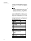
DO ENABLE/ALARM
HYSTERESIS X.XXX PPM
OPTIONAL OUTPUTS
• ANALOG OUTPUT • • SERIAL OUTPUT • • ALARM BOX •