4220 Flow Meter
Section 4 Submerged Probe Installation
4-7
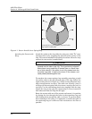
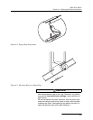
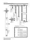
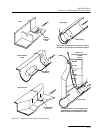
Assembling the Rings The scissors mechanism will work best if the respective assembly
is installed to allow the scissors to expand approximately in the
middle of the adjustment. Do not overtighten the mech-
anism. It is designed to flex somewhat to provide a positive lock,
once moderately tightened.
When assembling the ring sections, make sure the tongue sec-
tions are correctly inserted into the slotted sections. A flat blade
screwdriver can help slide the tongue sections through the slots
and over the securing buttons. In most cases, it is easiest to
assemble the base and extensions above ground, (without con-
necting into a circle), before entering the manhole. Then you can
pass it down into the manhole. (Do not drop it; this large
assembly can be badly bent.) Once maneuvered into the pipe, you
can install the scissors mechanism. Under varying conditions,
different pipes may require different ways to install the par-
ticular assembly.
Do not try to install the larger ring assemblies in pipes during
conditions of high flow. Always try to install during times of
lowest flow, for reasons of safety as well as ease of installation.
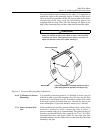
The hardware kit provides plastic cable ties to secure probe
cables along the back of the ring. It also includes flat head bolts
and nuts you can use to bolt sections of the ring assembly
together. This is recommended when installing the ring in larger
pipe sizes, where significant flow exists. Bolting the tongue sec-
tions together can greatly increase safety and prevent the
assembly from being torn apart.
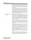
Attaching the Probe Remember that if the probe is not installed in the bottom center
of the channel, you must enter a zero level offset.
Note
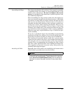
There are five pairs of countersunk holes on the base section
in-line with the mounting tabs. These holes are for use with
Isco’s Four-Foot Probe Extension only. Do not attempt to
use them to mount the probe carriers or the probes them-
selves.


