P6249 4 GHz 5X Active Probe Instruction Manual
35
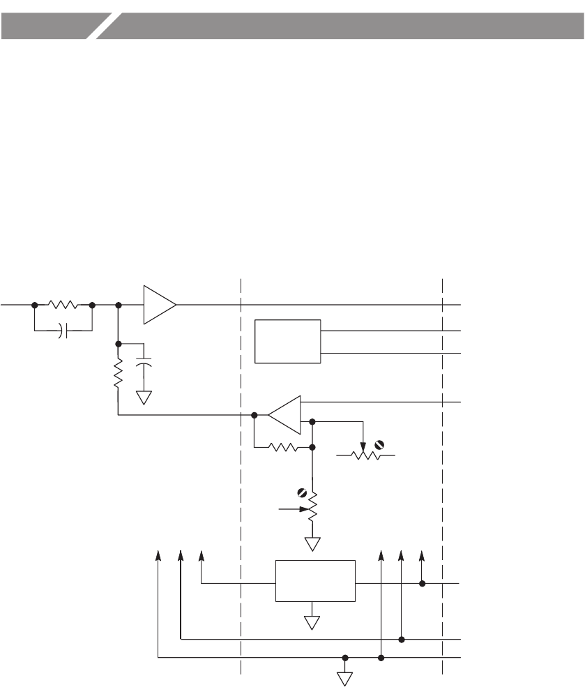
Theory of Operation
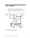
There are no user replaceable parts within the probe or the
compensation box; however, this theory of operation is provided to
assist you in isolating failures to either the probe or the host
oscilloscope. Refer to Figure 10 for the simplified schematic.
Offset
gain
Offset
zero
Offset ampifier
EEPROM
Offset to probe
Probe tip
amplifier
Signal Out
Probe tip
±1V Offset
Probe ID Out
+5V
–5V
Ground
Probe
cable
TEKPROBE
Interface
Probe head Compensation box Oscilloscope
Clock In
+5
–5
Linear
regulator
+7V
Figure 10: P6249 simplified schematic diagram


