Operating Basics
20
P6249 4 GHz 5X Active Probe Instruction Manual
Ground Lead Length
When you are probing a circuit, you should always use as short a
ground lead as possible between the probe head and circuit ground.
When you touch your probe tip to a circuit element, you are
introducing a new resistance, capacitance, and inductance into the
circuit. This represents the characteristics of your probe and ground
lead.
You can determine if ground lead effects may be a problem in your
application if you know the self-inductance (L) and capacitance (C)
of your probe and ground lead path. A portion of the ground lead
path is uncontrollable since it is hard-wired on the circuit board
under test.
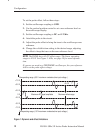
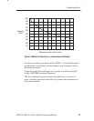
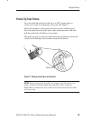
As a guide, refer to Figure 4 to estimate the maximum frequency you
can measure using additional lead length.
The total inductance can be calculated, with reference to the
measurement loop area formed by the ground lead path, using the
following formula:
L +
A
113
A = Measurement loop area in square inches
L = Inductance in microhenries
Once you have calculated the inductance, use 1 picofarad for the
capacitance of the P6249 and calculate the approximate resonant
frequency (f
0
) at which this parasitic circuit will resonate, using the
following formula:
f
0
+
1
2p LC
Ǹ
The preceding equation shows that reducing the ground lead
inductance will raise the resonant frequency. If your measurements
are affected by ringing, your goal is to lower the inductance of your
ground path until the resulting resonant frequency is at least 3 times
greater than the frequency of your measurements.


